Dodge Sprinter. Manual - part 286
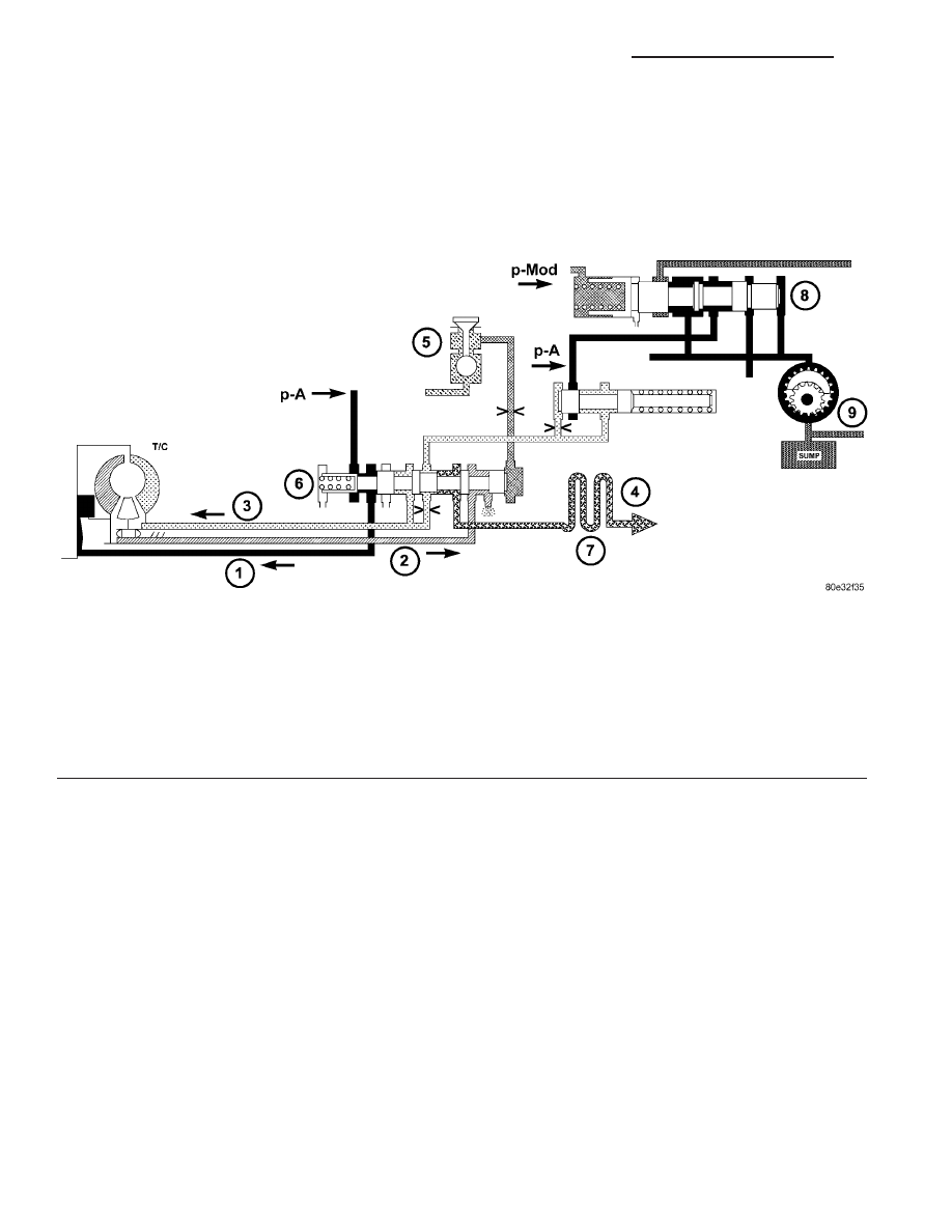
Torque Converter Lockup Clutch Regulating Valve
The torque converter lockup clutch regulating
valve (6) (Fig. 113) regulates the torque converter
lock-up clutch working pressure (p-TCC) in relation
to the torque converter clutch control pressure (p-S/
TCC). According to the size of the working pressure
(p-A), the torque converter lockup clutch is either
Engaged, Disengaged, or Slipping. When the regulat-
ing valve (6) is in the lower position, lubricating oil
flows through the torque converter and oil cooler (8)
into the transmission (torque converter lockup clutch
unpressurized). In its regulating position (slipping,
torque
converter
lockup
clutch
pressurized),
a
reduced volume of lubricating oil flows through the
annular passage (7) bypassing the torque converter
and passing direct through the oil cooler into the
transmission. The rest of the lubricating oil is
directed via the throttle “a” into the torque converter
in order to cool the torque converter lockup clutch.
Fig. 113 Torque Converter Lockup Clutch Regulating Valve
1 - TORQUE CONVERTER LOCK-UP CLUTCH
2 - TORQUE CONVERTER OUTPUT
3 - TORQUE CONVERTER INPUT
4 - LUBRICATION
5 - TORQUE CONVERTER LOCK-UP SOLENOID
6 - TORQUE CONVERTER LOCK-UP CLUTCH REGULATING
VALVE
7 - OIL COOLER
8 - LINE PRESSURE REGULATING VALVE
9 - OIL PUMP
21 - 114
AUTOMATIC TRANSMISSION NAG1 - SERVICE INFORMATION
VA