Dodge Sprinter. Manual - part 264


  Index      Dodge     Dodge Sprinter / Mercedes-Benz - service repair manual 2006 year


Search            


Content   ..  262  263  264  265   ..


Dodge Sprinter. Manual - part 264


Shift Phase - 1-2 Shift Phase 1

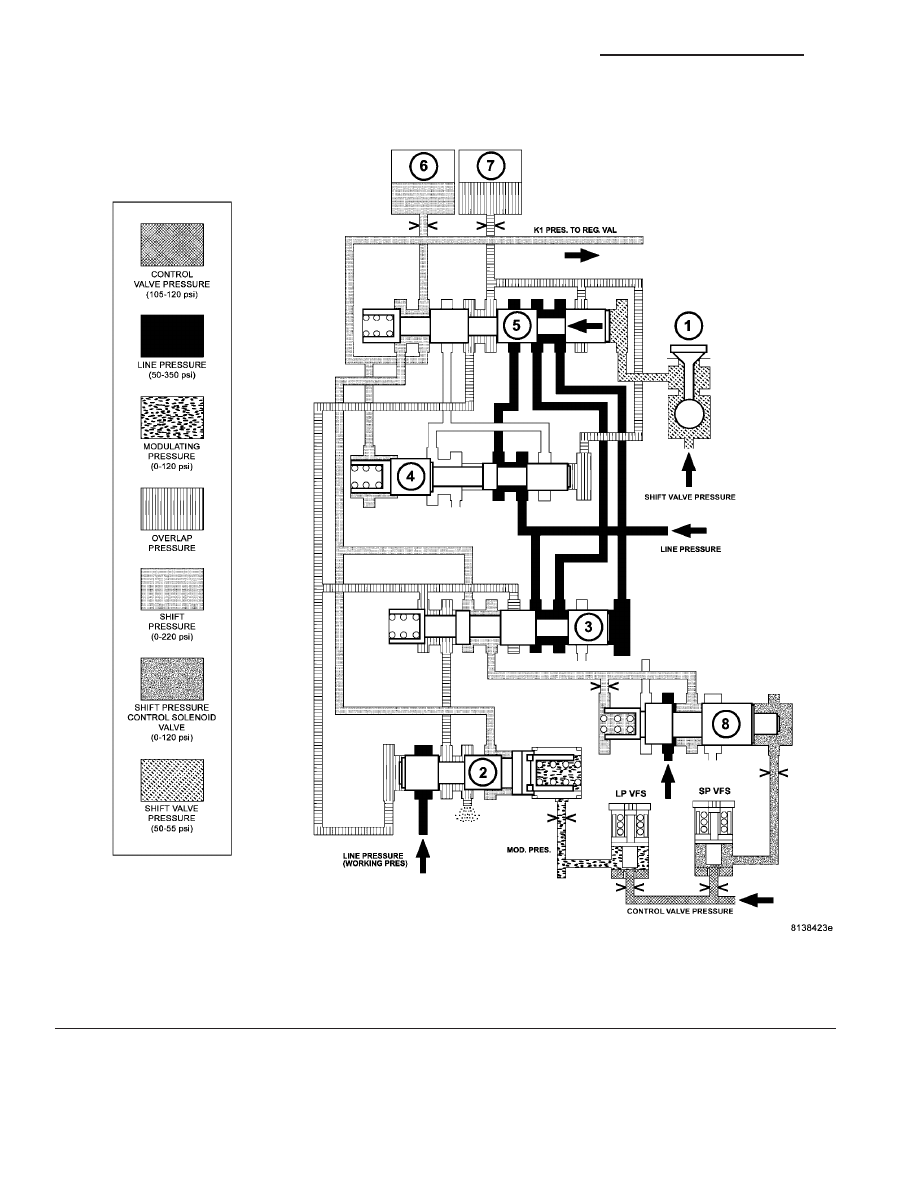
When the 1-2 and 4-5 shift solenoid valve (1) (Fig.

17) is turned on, the shift valve pressure (p-SV) is
directed onto the end face of the command valve (5).

The command valve is moved and the shift pressure
(p-S) coming from the shift pressure shift valve (3) is

Fig. 17 Shift Phase - 1-2 Shift Phase 1

1 - 1-2/4-5 SHIFT SOLENOID

5 - 1-2/4-5 COMMAND VALVE

2 - 1-2/4-5 OVERLAP VALVE

6 - DRIVING CLUTCH K1

3 - 1-2/4-5 SHIFT PRESSURE SHIFT VALVE

7 - HOLDING CLUTCH B1

4 - 1-2/4-5 HOLDING PRESSURE SHIFT VALVE

8 - SHIFT PRESSURE REGULATOR VALVE

21 - 26

AUTOMATIC TRANSMISSION NAG1 - SERVICE INFORMATION

VA

directed via the command valve (5) onto clutch K1
(6).

Simultaneously the clutch B1 (7) is subjected to

overlap pressure by the overlap regulating valve (2).
The pressure in the clutch B1 (7) as it disengages is
controlled during the shift phase depending on
engine load by the modulating pressure and the
applying clutch pressure (the shift pressure in clutch
K1). The controlled pressure in clutch B1 (7) is
inversely proportional to the capacity of the clutch
being engaged. The rising shift pressure (p-S) at
clutch K1 (6) acts on the annular face of the overlap
regulating valve (2) and reduces the overlap pressure
regulated by the overlap regulating valve (2). When a
corresponding pressure level is reached at the hold-
ing pressure shift valve (4), this valve switches over.

VA

AUTOMATIC TRANSMISSION NAG1 - SERVICE INFORMATION

21 - 27

Shift Phase - 1-2 Shift Phase 2

The B1 (7) (Fig. 18) pressure acting on the end face

of the shift pressure shift valve (3) is replaced by the
working pressure (p-A). The shift pressure is also

routed to the spring end of the holding valve (4) and
the holding valve downshifts. The line pressure is
then routed to the command valve (5).

Fig. 18 Shift Phase - 1-2 Shift Phase 2

1 - 1-2/4-5 SHIFT SOLENOID

5 - 1-2/4-5 COMMAND VALVE

2 - 1-2/4-5 OVERLAP VALVE

6 - DRIVING CLUTCH K1

3 - 1-2/4-5 SHIFT PRESSURE SHIFT VALVE

7 - HOLDING CLUTCH B1

4 - 1-2/4-5 HOLDING PRESSURE SHIFT VALVE

8 - SHIFT PRESSURE REGULATOR VALVE

21 - 28

AUTOMATIC TRANSMISSION NAG1 - SERVICE INFORMATION

VA

Second Gear Engaged

After the gearchange is complete, the pressure on

the end face of the command valve (5) (Fig. 19) is
reduced via the 1-2 and 4-5 shift solenoid valve (1),

and the command valve (5) is pushed back to its
basic position. Via the holding pressure shift valve
(4) the working pressure (p-A) now passes via the

Fig. 19 Second Gear Engaged

1 - 1-2/4-5 SHIFT SOLENOID

5 - 1-2/4-5 COMMAND VALVE

2 - 1-2/4-5 OVERLAP VALVE

6 - DRIVING CLUTCH K1

3 - 1-2/4-5 SHIFT PRESSURE SHIFT VALVE

7 - HOLDING CLUTCH B1

4 - 1-2/4-5 HOLDING PRESSURE SHIFT VALVE

8 - SHIFT PRESSURE REGULATOR VALVE

VA

AUTOMATIC TRANSMISSION NAG1 - SERVICE INFORMATION

21 - 29


Content   ..  262  263  264  265   ..