Index Dodge Dodge Sprinter / Mercedes-Benz - service repair manual 2006 year
Search
Content .. 238 239 240 241 ..
Dodge Sprinter. Manual - part 240
Fig.
6
0
5
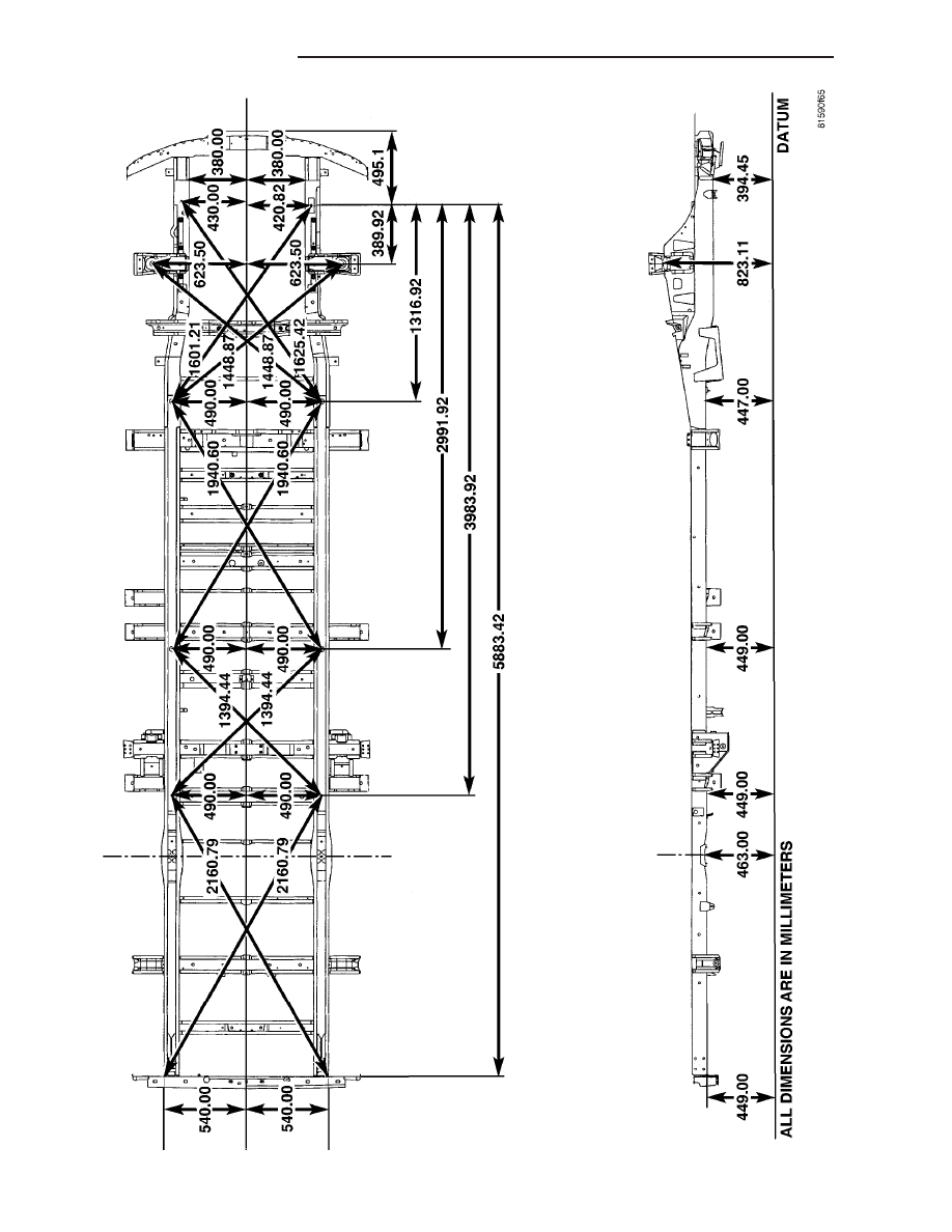
FRAME
DIMENSIONS
2
13 - 6
FRAME & BUMPERS
VA