Dodge Sprinter. Manual - part 31


  Index      Dodge     Dodge Sprinter / Mercedes-Benz - service repair manual 2006 year


Search            


Content   ..  29  30  31  32   ..


Dodge Sprinter. Manual - part 31


Propylene - glycol / Ethylene - glycol Mixtures - Should Not
Be Used in Chrysler Vehicles

Propylene-glycol/ethylene-glycol

Mixtures

can

cause the destabilization of various corrosion inhibi-
tors, causing damage to the various cooling system
components. Also, once ethylene-glycol and propy-
lene-glycol based coolants are mixed in the vehicle,
conventional methods of determining freeze point will
not be accurate. Both the refractive index and spe-
cific gravity differ between ethylene glycol and propy-
lene glycol.

CAUTION: Richer antifreeze mixtures cannot be
measured with normal field equipment and can
cause problems associated with 100 percent ethyl-
ene-glycol.

DIAGNOSIS AND TESTING

COOLING SYSTEM LEAKS

ULTRAVIOLET LIGHT METHOD

A leak detection additive is available through the

parts department that can be added to cooling sys-
tem. The additive is highly visible under ultraviolet
light (black light). Pour one ounce of additive into
cooling system. Place heater control unit in HEAT
position. Start and operate engine until radiator
upper hose is warm to touch. Aim the commercially
available black light tool at components to be
checked. If leaks are present, black light will cause
additive to glow a bright green color.

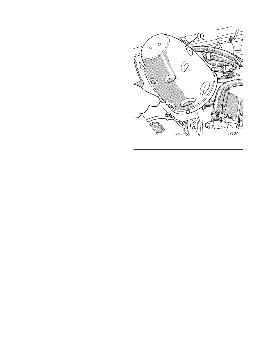
The black light can be used in conjunction with a

pressure tester to determine if any external leaks
exist (Fig. 1).

PRESSURE TESTER METHOD

The engine should be at normal operating temper-

ature. Recheck the system cold if cause of coolant
loss is not located during the warm engine examina-
tion.

WARNING: Hot, pressurized coolant can cause
injury by scalding.

Carefully remove coolant recovery pressure con-

tainer cap and check coolant level. Push down on cap
to disengage it from stop tabs. Wipe inside of con-
tainer and examine lower inside sealing seat for
nicks, cracks, paint, dirt and solder residue. Inspect
radiator-to- pressure container hose for internal
obstructions. Insert a wire through the hose to be
sure it is not obstructed.

Inspect cams on outside of pressure container. If

cams are damaged, seating of pressure cap valve and
tester seal will be affected.

Attach pressure tester (7700 or an equivalent) to

coolant pressure container (Fig. 2).

Fig. 1 Leak Detection Using Black Light - Typical

1 - TYPICAL BLACK LIGHT TOOL

7 - 10

ENGINE

VA

Operate tester pump to apply 103.4 kPa (15 psi)

pressure to system. If hoses enlarge excessively or
bulges while testing, replace as necessary. Observe
gauge pointer and determine condition of cooling sys-
tem according to following criteria:

Holds Steady: If pointer remains steady for two

minutes, serious coolant leaks are not present in sys-
tem. However, there could be an internal leak that
does not appear with normal system test pressure. If
it is certain that coolant is being lost and leaks can-
not be detected, inspect for interior leakage or per-
form Internal Leakage Test.

Drops Slowly: Indicates a small leak or seepage

is occurring. Examine all connections for seepage or
slight leakage with a flashlight. Inspect radiator,
hoses, gasket edges and heater. Seal small leak holes
with a Sealer Lubricant (or equivalent). Repair leak
holes

and

inspect

system

again

with

pressure

applied.

Drops Quickly: Indicates that serious leakage is

occurring. Examine system for external leakage. If
leaks are not visible, inspect for internal leakage.
Large radiator leak holes should be repaired by a
reputable radiator repair shop.

INTERNAL LEAKAGE INSPECTION

Remove engine oil pan drain plug and drain a

small amount of engine oil. If coolant is present in
the pan, it will drain first because it is heavier than
oil. An alternative method is to operate engine for a
short period to churn the oil. After this is done,
remove engine dipstick and inspect for water glob-

ules. Also inspect transmission dipstick for water
globules and transmission fluid cooler for leakage.

WARNING: WITH RADIATOR PRESSURE TESTER
TOOL INSTALLED ON RADIATOR, DO NOT ALLOW
PRESSURE TO EXCEED 110 KPA (20 PSI). PRES-
SURE WILL BUILD UP QUICKLY IF A COMBUSTION
LEAK

IS

PRESENT.

TO

RELEASE

PRESSURE,

ROCK

TESTER

FROM

SIDE

TO

SIDE.

WHEN

REMOVING TESTER, DO NOT TURN TESTER MORE
THAN 1/2 TURN IF SYSTEM IS UNDER PRESSURE.

Operate engine without pressure cap on coolant

container until thermostat opens. Attach a Pressure
Tester to container. If pressure builds up quickly it
indicates a combustion leak exists. This is usually
the result of a cylinder head gasket leak or crack in
engine. Repair as necessary.

If there is not an immediate pressure increase,

pump the Pressure Tester. Do this until indicated
pressure is within system range of 110 kPa (16 psi).
Fluctuation of gauge pointer indicates compression or
combustion leakage into cooling system.

Because the vehicle is equipped with a catalytic

converter, do not remove spark plug cables or short
out cylinders to isolate compression leak.

If the needle on dial of pressure tester does not

fluctuate, race engine a few times to check for an
abnormal amount of coolant or steam. This would be
emitting from exhaust pipe. Coolant or steam from
exhaust pipe may indicate a faulty cylinder head gas-
ket, cracked engine cylinder block or cylinder head.

A convenient check for exhaust gas leakage into

cooling system is provided by a commercially avail-
able Block Leak Check tool. Follow manufacturers
instructions when using this product.

COMBUSTION LEAKAGE TEST - WITHOUT PRES-
SURE TESTER

DO NOT WASTE reusable coolant. If solution is

clean, drain coolant into a clean and suitably marked
container for reuse.

WARNING: Do not remove cylinder block drain
plugs or loosen radiator drain with system hot and
under pressure. serious burns from coolant can
occur.

Drain

sufficient

coolant

to

allow

thermostat

removal.

Remove accessory drive belt.
Add coolant to pressure container to bring level to

within 6.3 mm (1/4 in) of top of thermostat housing.

CAUTION:

Avoid

overheating.

Do

not

operate

engine for an excessive period of time. Open drain-
cock immediately after test to eliminate boil over.

Fig. 2 PRESSURE TESTING

1 - PRESSURE RESERVOIR CAP
2 - PRESSURE RESERVOIR
3 - PRESSURE TESTER

VA

ENGINE

7 - 11

Start engine and accelerate rapidly three times, to

approximately 3000 rpm while observing coolant. If
internal engine combustion gases are leaking into
cooling system, bubbles will appear in coolant. If bub-
bles do not appear, internal combustion gas leakage
is not present.

STANDARD PROCEDURE

ADDING ADDITIONAL COOLANT

The use of aluminum cylinder blocks, cylinder

heads and water pumps requires special corrosion
protection.

Only

Mopar

t Antifreeze/Coolant, 5

Year/100,000 Mile Formula (glycol base coolant with
corrosion inhibitors called HOAT, for Hybrid Organic
Additive Technology) is recommended. This coolant
offers the best engine cooling without corrosion when
mixed with 50% distilled water to obtain to obtain a
freeze point of -37°C (-35°F). If it loses color or
becomes contaminated, drain, flush, and replace with
fresh properly mixed coolant solution.

CAUTION: Do not use coolant additives that are
claimed to improve engine cooling.

DRAINING COOLING SYSTEM

WARNING: Do not remove the cylinder block drain
plug or loosen the radiator drain plug with system
hot and under pressure. Serious burns from coolant
can occur.

(1) DO NOT remove coolant recovery pressure con-

tainer cap first. With engine cold, raise vehicle on a
hoist and locate radiator draincock.

NOTE: Radiator draincock is located on the left/
lower side of radiator.

(2) Attach one end of a hose to the draincock (Fig.

3). Put the other end into a clean and appropriately
marked container. Open draincock and drain coolant
from radiator. This will empty the coolant recovery
pressure container first. The coolant does not have to
be removed from the container unless the system is
being refilled with a fresh mixture. When container
is empty, remove cap and continue draining cooling
system.

To drain the engine of coolant, loosen the cylinder

block drain plug located on the side of cylinder block
(Fig. 3).

7 - 12

ENGINE

VA

REFILLING COOLING SYSTEM

(1) Tighten the radiator drain and the cylinder

block drain plug(s) (if removed). Tighten the engine
drain plug to 30 N·m (22 lbs. ft.).

(2) Fill system using a 50/50 mixture of ethylene-

glycol antifreeze and low mineral content water. Fill
radiator to top and add sufficient coolant to the cool-
ant recovery pressure container to raise level to
COLD MINIMUM mark.

(3) With heater control unit in the HEAT position,

operate engine with container cap in place.

(4) After engine has reached normal operating

temperature, shut engine off and allow it to cool.
When engine is cooling down, coolant will be drawn
into the radiator from the pressure container.

(5) Add coolant to pressure container as necessary.

Only add coolant to the container when the
engine is cold. Coolant level in a warm engine
will be higher due to thermal expansion. 
To
purge the cooling system of all air, this heat up/cool
down cycle (adding coolant to cold engine) must be
performed three times. Add necessary coolant to raise

container level to the COLD MINIMUM mark after
each cool down period.

COOLANT LEVEL SENSOR

REMOVAL

WARNING: Risk of injury to skin and eyes due to
scalding from hot coolant. Do not open the cooling
system unless the temperature is below 194°f
(90°c). Wear protective clothing and eye wear. Risk
of poisoning if coolant is swallowed. Store coolant
in proper and appropriately marked containers.

NOTE: Drain coolant from radiator drain plug only.

(1) Drain coolant until the coolant reservoir is

emptied.

(2) Disconnect the wiring harness electrical con-

nector.

Fig. 3 DRAINING COOLANT SYSTEM

1 - DRAIN HOSE

3 - RADIATOR DRAIN PLUG

2 - ENGINE DRAIN PLUG

4 - DRAIN HOSE

VA

ENGINE

7 - 13


Content   ..  29  30  31  32   ..