Dodge Ram Truck 1500-2500-3500. Manual - part 875
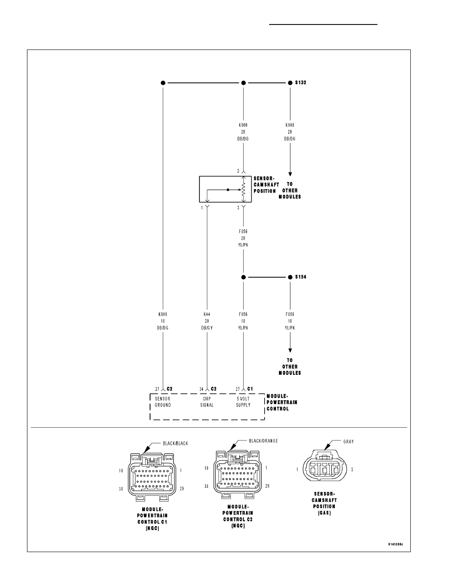
P0340-CAMSHAFT POSITION SENSOR CIRCUIT
9 - 422
ENGINE - ELECTRICAL DIAGNOSTICS - 3.7L/4.7L/5.7L
DR/DH
|
|
|
P0340-CAMSHAFT POSITION SENSOR CIRCUIT 9 - 422 ENGINE - ELECTRICAL DIAGNOSTICS - 3.7L/4.7L/5.7L DR/DH |