Dodge Ram Truck 1500-2500-3500. Manual - part 441
OPERATION
The standard 4-pin trailer tow connector contains the following vehicle circuits: park/tail lamps, left stop/turn lamp,
right stop/turn lamp, and ground. The optional trailer towing package 7-way connector contains the same circuits as
the 4-pin connector plus the following additional circuits: backup lamp, trailer battery and electric brake.
If an aftermarket electric brake controller is used, the electric brake pigtail harness supplied will make installation
easier. The connection (blue 4-way connector) for the harness is located under the instrument panel to the left of
the brake pedal on top of the large body harness connection. Refer to the appropriate wiring information.
The battery line of this harness may be used to charge the trailer battery. However, a battery isolation unit is not
supplied and the trailer battery may discharge the truck battery while the engine is not running. The battery line is
protected by a fuse or a circuit breaker. Refer to the owner’s manual in the vehicle glove box for type, location, and
ampere rating of the fuse or circuit breaker.
CAM-TURN SIGNAL CANCEL
DESCRIPTION
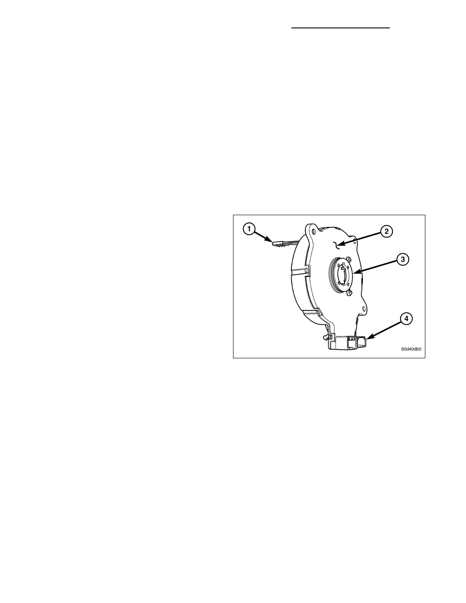
The turn signal cancel cam (3) is concealed within the
steering column. The turn signal cancel cam consists
of two lobes on a molded plastic ring that is snapped
into the lower hub of the clockspring rotor. The clock-
spring mechanism provides turn signal cancellation as
well as a constant electrical connection between the
horn switch, driver airbag, speed control switches, and
remote radio switches on the steering wheel and the
instrument panel wire harness on the steering column.
The housing of the clockspring (2) is secured to the
multi-function switch mounting housing on the steering
column and remains stationary. The rotor of the clock-
spring, including the turn signal cancel cam lobes
rotate with the steering wheel.
The turn signal cancel cam is serviced as a unit with
the clockspring and cannot be repaired. If faulty or
damaged,
the
entire
clockspring
unit
must
be
replaced. (Refer to 8 - ELECTRICAL/RESTRAINTS/CLOCKSPRING - REMOVAL).
OPERATION
When the multi-function switch control stalk is moved to a latched turn signal position, a turn signal cancel actuator
is extended from the inside surface of the switch housing toward the turn signal cancel cam. As the steering wheel
is rotated to complete the turn, one of the two cam lobes will contact the actuator, automatically cancelling the turn
signal event and releasing the latched multi-function switch control stalk to the neutral position.
8L - 170
LAMPS/LIGHTING - EXTERIOR - SERVICE INFORMATION
DR/DH