Content .. 2035 2036 2037 2038 ..
Dodge Ram Truck 1500-2500-3500. Manual - part 2037
*ACTUATOR CIRCUIT TEST DIAGNOSTICS (SINGLE-ZONE) (CONTINUED)
For the Manual Temperature Control circuit diagrams (Refer to 24 - HEATING & AIR CONDITIONING - SCHEMAT-
ICS AND DIAGRAMS).
For a complete wiring diagram Refer to Section 8W.
Theory of Operation
By running the Actuator Circuit Test, the A/C Heater Control can identify up to three door driver circuits shorted
simultaneously. A Short Too Complex fault will set if more than three door driver circuits are shorted in the same
direction (e.g. four door driver circuits all shorted to ground) or if two or more door driver circuits are shorted with
at least one door driver circuit shorted to ignition and one door driver circuit shorted to ground. Fault messages
displaying XXX Driver/Circuit Shorted to Ignition/Battery and XXX Driver/Circuit Shorted to Ground will set on a per-
driver basis. Fault messages displaying the same two drivers/circuits shorted to ignition/battery as-well-as shorted to
ground indicates that two actuator driver circuits are shorted together. To ensure a proper diagnosis, repair all Short
Too Complex fault messages first, all common door driver circuit related fault messages second, and all other fault
messages last. In addition, always test the door driver circuits after each repair by cycling the ignition switch and
then running the Actuator Circuit Test again to ensure that no new faults exits.
Diagnostic Test
1.
SELECT THE CORRECT PROCEDURE STEPS TO DIAGNOSE THE ACTUATOR CIRCUIT TEST FAULT(S)
Which Actuator Circuit Test message is present?
XXX Driver/Circuit Shorted to Ground
Go To 2
XXX Driver/Circuit Shorted to Ignition or Battery
Go To 4
Short Too Complex
Go To 6
XXX Driver/Circuit Shorted to Ground & to Ignition or Battery
Go To 8
2.
CHECK THE DOOR DRIVER CIRCUIT IDENTIFIED IN THE ACTUATOR CIRCUIT TEST MESSAGE FOR A
SHORT TO GROUND
Turn the ignition off.
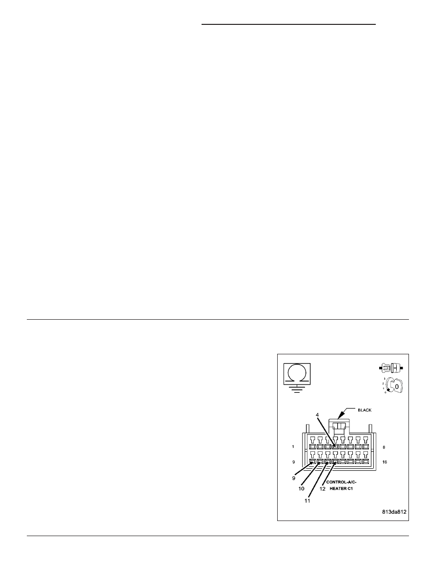
Disconnect the A/C Heater Control C1 harness connector.
Measure the resistance of the applicable door driver circuit between
ground and the A/C Heater Control C1 harness connector.
Is the resistance below 10k ohms?
Yes
>> Repair the door driver circuit for a short to ground.
Perform BODY VERIFICATION TEST - VER 1. (Refer to 8
-
ELECTRICAL/ELECTRONIC
CONTROL
MODULES/
FRONT CONTROL MODULE - DIAGNOSIS AND TEST-
ING).
No
>> Go To 3
24 - 148
HVAC - ELECTRICAL DIAGNOSTICS
DR/DH