Content .. 1781 1782 1783 1784 ..
Dodge Ram Truck 1500-2500-3500. Manual - part 1783
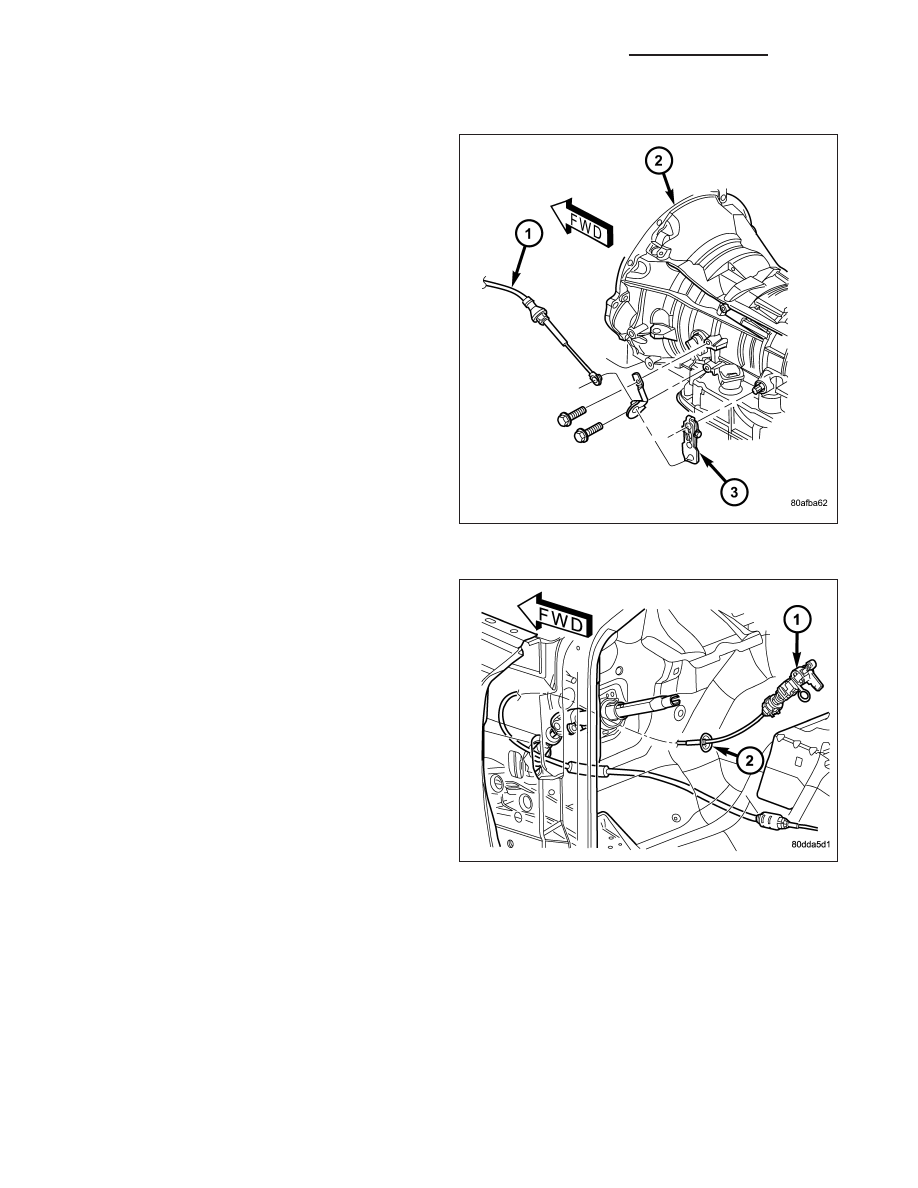
REMOVAL
1. Shift transmission into PARK.
2. Raise vehicle.
3. Disengage cable (1) eyelet at transmission manual
shift lever (3) and pull cable adjuster out of mount-
ing bracket.
4. Lower the vehicle.
5. Remove the dash panel insulation pad as neces-
sary to access the gearshift cable grommet (2).
6. Remove grommet (2) from the dash panel.
21 - 1064
AUTOMATIC TRANSMISSION - 48RE - SERVICE INFORMATION
DR/DH