Dodge Ram Truck 1500-2500-3500. Manual - part 1338


  Index      Dodge     Dodge Ram Truck 1500-2500-3500 - service repair manual 2005 year


Search            


Content   ..  1336  1337  1338  1339   ..


Dodge Ram Truck 1500-2500-3500. Manual - part 1338


COVER - TIMING

REMOVAL

1. Disconnect the battery negative cable.

2. Drain cooling system (Refer to 7 - COOLING -

STANDARD PROCEDURE).

3. Disconnect both heater hoses at timing cover.

4. Disconnect lower radiator hose at engine.

5. Remove crankshaft damper (Refer to 9 - ENGINE/

ENGINE

BLOCK/VIBRATION

DAMPER

-

REMOVAL).

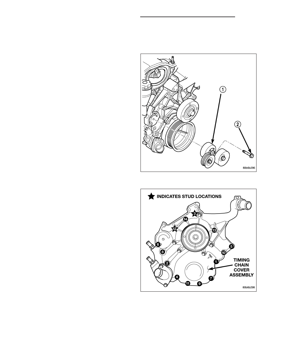
6. Remove accessory drive belt tensioner assembly

(1).

7. Remove the generator and A/C compressor.

CAUTION: The 4.7L engine uses an RTV sealer
instead of a gasket to seal the front cover to the
engine block, from the factory. For service, Mopar

T

Grey Engine RTV sealant must be substituted.

NOTE: It is not necessary to remove the water
pump for timing cover removal.

8. Remove the bolts holding the timing cover to

engine block.

9. Remove cover.

9 - 2274

ENGINE - 4.7L - SERVICE INFORMATION

DR/DH

INSTALLATION

CAUTION: Do not use oil based liquids to clean
timing cover or block surfaces. Use only rubbing
alcohol, along with plastic or wooden scrapers.
Use no wire brushes or abrasive wheels or metal
scrapers, or damage to surfaces could result.

1. Clean timing chain cover and block surface using

rubbing alcohol.

CAUTION: The 4.7L can use a special RTV sealer
instead of a carrier gasket to seal the timing cover
to the engine block, from the factory. For service
repairs, Mopar

T

Grey Engine RTV must be used as

a substitute, if RTV is present. If the front cover
being used has no provisions for the water pas-
sage o-rings, then Mopar

T

Grey Engine RTV must

be applied around the water passages.

2. Inspect the water passage o-rings, if equipped for

any damage, and replace as necessary.

3. Apply Mopar

T

Grey Engine RTV sealer to the front

cover following the path above, using a 3 to 4mm
thick bead.

4. Install cover. Tighten flange head fasteners in

sequence as shown in to 58 N·m (43 ft. lbs.).

5. Install the A/C compressor and generator.

6. Install crankshaft damper (Refer to 9 - ENGINE/

ENGINE BLOCK/VIBRATION DAMPER - INSTAL-
LATION).

7. Install accessory drive belt tensioner assembly.

Tighten fastener to 54 N·m (40 ft. lbs.).

8. Install lower radiator hose.

9. Install both heater hoses.

10. Fill cooling system (Refer to 7 - COOLING -

STANDARD PROCEDURE).

11. Connect the battery negative cable.

DR/DH

ENGINE - 4.7L - SERVICE INFORMATION

9 - 2275

TIMING CHAIN & SPROCKETS

REMOVAL

1. Disconnect negative cable from battery.

2. Drain cooling system (Refer to 7 - COOLING -

STANDARD PROCEDURE).

3. Remove right and left cylinder head covers (Refer

to

9

-

ENGINE/CYLINDER

HEAD/CYLINDER

HEAD COVER(S) - REMOVAL).

4. Remove radiator fan shroud.

5. Rotate engine until timing mark (2) on crankshaft

damper aligns with TDC mark on timing chain
cover (2) (#1 cylinder exhaust stroke) and the cam-
shaft sprocket “V8” marks are at the 12 o’clock
position (1,2).

9 - 2276

ENGINE - 4.7L - SERVICE INFORMATION

DR/DH

6. Remove power steering pump (Refer to 19 -

STEERING/PUMP - REMOVAL).

7. Remove access plugs (1,2) from left and right cyl-

inder heads for access to chain guide fasteners.

8. Remove the oil fill housing to gain access to the

right side tensioner arm fastener.

9. Remove crankshaft damper (Refer to 9 - ENGINE/

ENGINE

BLOCK/VIBRATION

DAMPER

-

REMOVAL) and timing chain cover (Refer to 9 -
ENGINE/VALVE TIMING/TIMING BELT / CHAIN
COVER(S) - REMOVAL).

10. Collapse and pin primary chain tensioner (1).

CAUTION: Plate behind left secondary chain ten-
sioner could fall into oil pan. Therefore, cover pan
opening.

11. Remove secondary chain tensioners.

DR/DH

ENGINE - 4.7L - SERVICE INFORMATION

9 - 2277


Content   ..  1336  1337  1338  1339   ..