Dodge Neon / Neon SRT-4. Manual - part 431


  Index      Dodge     Dodge Neon / Neon SRT-4 - service repair manual 2005 year


Search            


Content   ..  429  430  431  432   ..


Dodge Neon / Neon SRT-4. Manual - part 431


HVAC HOUSING

REMOVAL

WARNING: On vehicles equipped with airbags, dis-
able the airbag system before attempting any steer-
ing wheel, steering column, or instrument panel
component diagnosis or service. Disconnect and
isolate the battery negative (ground) cable, then
wait two minutes for the airbag system capacitor to
discharge before performing further diagnosis or
service. This is the only sure way to disable the air-
bag system. Failure to take the proper precautions
could result in an accidental airbag deployment and
possible personal injury or death.

WARNING: Refer to the applicable warnings and
cautions for this system before performing the fol-
lowing operation (Refer to 24 - HEATING & AIR
CONDITIONING/PLUMBING - WARNINGS) and (Refer
to 24 - HEATING & AIR CONDITIONING/PLUMBING -
CAUTIONS). Failure to follow the warnings and cau-
tions could result in possible personal injury or
death.

NOTE: The HVAC housing must be removed from
the vehicle and the two halves of the housing sep-
arated for service access of the heater core, A/C

evaporator and the mode, recirculation and blend-
air doors.

(1) Recover the refrigerant from the refrigerant

system (Refer to 24 - HEATING & AIR CONDITION-
ING/PLUMBING

-

STANDARD

PROCEDURE

-

REFRIGERANT SYSTEM RECOVERY).

(2) Partially

drain

the

engine

cooling

system

(Refer to 7 - COOLING/ENGINE/COOLANT - STAN-
DARD PROCEDURE - DRAINING COOLING SYS-
TEM).

(3) Disconnect and isolate the negative battery

cable.

(4) Remove the coolant recovery container (Refer

to 7 - COOLING/ENGINE/COOLANT RECOVERY
CONTAINER - REMOVAL).

(5) Remove the screw that secures the accumulator

mounting bracket to the body.

(6) Remove the two bolts securing the accumulator

tubes to the evaporator terminal block and discon-
nect the tubes from the terminal block.

(7) Remove the seals from the refrigerant lines fit-

tings and discard.

(8) Install plugs in, or tape over all of the opened

refrigerant line fittings and evaporator tubes.

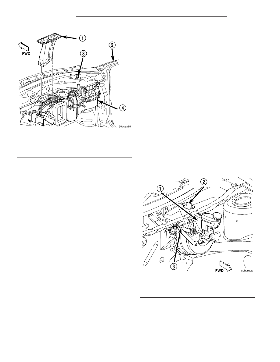
(9) Disconnect the vacuum harness at the power

brake booster (Fig. 7).

(10) Remove the rubber drain tube extension from

the condensation drain tube (Fig. 8).

(11) Disconnect the heater hoses from the heater

core tubes. Install plugs in, or tape over the opened
heater core tubes to prevent coolant spillage during
housing removal.

Fig. 6 Defroster Duct - Typical

1 - DEFROSTER DUCT
2 - BODY
3 - ELECTRICAL CONNECTOR
4 - HVAC HOUSING

Fig. 7 A/C Vacuum Line - LHD Shown, RHD Typical

1 - BRAKE POWER BOOSTER
2 - A/C VACUUM CHECK VALVE
3 - VACUUM HARNESS

24 - 32

DISTRIBUTION

PL/SRT-4

DEFROSTER DUCT (Continued)

(12) Remove three HVAC housing retaining nuts

located on the dash panel in the engine compart-
ment.

(13) Remove the instrument panel from vehicle

(Refer to 23 - BODY/INSTRUMENT PANEL/IN-
STRUMENT PANEL ASSEMBLY - REMOVAL).

(14) Remove the mode door and temperature con-

trol cables from the mode door and blend-air door
levers and the HVAC housing (Refer to 24 - HEAT-
ING

& AIR

CONDITIONING/CONTROLS/MODE

DOOR CABLE - REMOVAL) and (Refer to 24 -
HEATING

&

AIR

CONDITIONING/CONTROLS/

TEMPERATURE CONTROL CABLES - REMOVAL).

(15) Remove the defroster and floor distribution

ducts from the HVAC housing (Refer to 24 - HEAT-
ING & AIR CONDITIONING/DISTRIBUTION/DE-
FROSTER DUCTS - REMOVAL) and (Refer to 24 -
HEATING & AIR CONDITIONING/DISTRIBUTION/
FLOOR DISTRIBUTION DUCTS - REMOVAL).

(16) Disconnect the wire harness connectors.
(17) Remove the outboard HVAC housing retaining

screw located in the passenger compartment (Fig. 9).

(18) Remove the remaining nut located on the

dash panel stud.

NOTE: Use care to ensure that the interior is cov-
ered in case of loss of residual fluids from the
heater and evaporator cores.

(19) Remove the HVAC housing from the vehicle.

DISASSEMBLY

(1) Remove the HVAC housing from the vehicle

(Refer to 24 - HEATING & AIR CONDITIONING/
DISTRIBUTION/HVAC HOUSING - REMOVAL).

(2) Place the HVAC housing in the upright position

on a workbench, making allowance for leakage of flu-
ids.

(3) Separate the air distribution foam seals at the

case parting line (Fig. 10).

(4) Remove the evaporator and heater core tube

foam seals from the housing (Fig. 11).

(5) Remove the retaining clips and screws that

hold the upper and lower housing together.

(6) Separate the two halves of the housing.
(7) Remove the heater core and evaporator from

the lower housing as necessary.

ASSEMBLY

(1) Install the heater and evaporator cores into the

case as necessary.

(2) Position the upper and lower HVAC housings

together.

(3) Install the retaining clips and screws that

secure the upper and lower case housings together.
Tighten the screws to 2 N·m 17 in. lbs.).

(4) Install the evaporator and heater core tube

foam seals onto the housing.

(5) Connect the air distribution outlet foam seals

at the case parting line.

Fig. 8 Dash Panel - LHD Shown, RHD Typical

1 - BLOWER RESISTOR
2 - EVAPORATOR TAPPING PLATE
3 - DRAIN TUBE
4 - DASH PANEL
5 - HEATER HOSES
6 - RETAINING NUTS (3)

Fig. 9 Housing Screws-LHD Shown, RHD Typical

1 - OUTBOARD RETAINING SCREW
2 - HOUSING SCREW BOSSES
3 - DASH PANEL STUD AND NUT

PL/SRT-4

DISTRIBUTION

24 - 33

HVAC HOUSING (Continued)

(6) Install the HVAC housing (Refer to 24 - HEAT-

ING & AIR CONDITIONING/DISTRIBUTION/HVAC
HOUSING - INSTALLATION).

INSTALLATION

NOTE: High pressures are produced in the refriger-
ant system when the air conditioning compressor is
operating. Extreme care must be exercised to make
sure that each of the refrigerant system connec-
tions is pressure-tight and leak free.

(1) Position the HVAC housing to the dash panel.
(2) Install the nut onto the dash panel stud.

Tighten the nut to 4.5 N·m (40 in. lbs.).

(3) Install the outboard HVAC housing retaining

bolt. Tighten the bolt to 4.5 N·m (40 in. lbs.).

(4) Connect the wire harness connectors.
(5) Install the defroster and floor distribution

ducts onto the HVAC housing (Refer to 24 - HEAT-
ING & AIR CONDITIONING/DISTRIBUTION/DE-
FROSTER DUCTS - INSTALLATION) and (Refer to
24 - HEATING & AIR CONDITIONING/DISTRIBU-
TION/FLOOR DISTRIBUTION DUCTS - INSTAL-
LATION).

(6) Loosely install the mode door and temperature

control cables to the mode door and blend-air door
levers and to the HVAC housing (Refer to 24 - HEAT-
ING

& AIR

CONDITIONING/CONTROLS/MODE

DOOR CABLE - INSTALLATION) and (Refer to 24 -
HEATING

&

AIR

CONDITIONING/CONTROLS/

TEMPERATURE CONTROL CABLES - INSTALLA-
TION).

(7) Install the instrument panel (Refer to 23 -

BODY/INSTRUMENT

PANEL/INSTRUMENT

PANEL ASSEMBLY - INSTALLATION) and adjust
the mode and temperature control cables.

(8) Install the three HVAC housing retaining nuts

onto the housing studs in the engine compartment.
Tighten the nuts to 4.5 N·m (40 in. lbs.).

(9) Unplug or remove the tape from the heater

core hoses and tubes.

(10) Connect the heater hoses to the heater core

tubes and install the heater hose clamps.

(11) Install the rubber drain tube extension onto

the condensation drain tube.

(12) Connect the vacuum harness at the brake

booster.

(13) Unplug or remove the tape from the opened

refrigerant line fittings.

(14) Lubricate two new rubber O-ring seals with

clean refrigerant oil and install them onto the accu-
mulator tube fittings.

(15) Connect the accumulator tubes to the evapo-

rator terminal block.

Fig. 10 HVAC Air Distribution Foam Seals - LHD

Shown, RHD Typical

1 - AIR DISTRIBUTION
2 - RECIRCULATION DOOR VACUUM ACTUATOR
3 - AIR INLET
4 - BLOWER MOTOR
5 - CONTROL CABLES
6 - VACUUM HARNESS

Fig. 11 Lower HVAC Housing - LHD Shown, RHD

Typical

1 - EVAPORATOR AND CONNECTION
2 - FOAM SEALS
3 - HEATER CORE AND TUBES
4 - HVAC HOUSING LOWER CASE
5 - HOUSING MOUNTING STUDS
6 - HOUSING DRAIN
7 - WIRING
8 - BLOWER MOTOR AND WHEEL

24 - 34

DISTRIBUTION

PL/SRT-4

HVAC HOUSING (Continued)

(16) Install the two bolts securing the refrigerant

lines to the evaporator tube tapping plate. Tighten
the bolts to 10 N·m (88 in. lbs.).

(17) Install the bolt securing the accumulator

mounting bracket. Tighten the bolt to 11 N·m (97 in.
lbs.).

(18) Position and install the coolant recovery con-

tainer (Refer to 7 - COOLING/ENGINE/COOLANT
RECOVERY CONTAINER - INSTALLATION).

(19) Reconnect the negative battery cable.
(20) If the heater core is being replaced, flush the

cooling system (Refer to 7 - COOLING - STANDARD
PROCEDURE - COOLING SYSTEM CLEANING/
REVERSE FLUSHING).

(21) Refill the engine cooling system (Refer to 7 -

COOLING/ENGINE - STANDARD PROCEDURE).

(22) Evacuate the refrigerant system (Refer to 24 -

HEATING & AIR CONDITIONING - STANDARD
PROCEDURE).

(23) Charge the refrigerant system (Refer to 24 -

HEATING & AIR CONDITIONING - STANDARD
PROCEDURE).

(24) Start the engine and check for proper opera-

tion of the heating and air conditioning systems as
equipped.

PL/SRT-4

DISTRIBUTION

24 - 35

HVAC HOUSING (Continued)


Content   ..  429  430  431  432   ..