Dodge Neon / Neon SRT-4. Manual - part 347


  Index      Dodge     Dodge Neon / Neon SRT-4 - service repair manual 2005 year


Search            


Content   ..  345  346  347  348   ..


Dodge Neon / Neon SRT-4. Manual - part 347


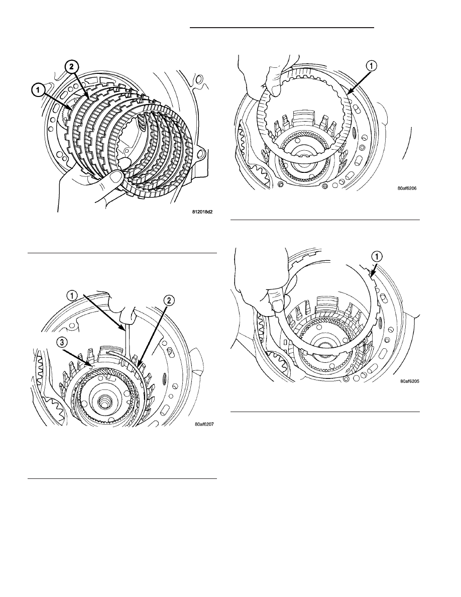
(39) Install low/reverse reaction plate flat snap

ring
(Fig. 118).

(40) Install remaining low/reverse clutch disc

(Fig. 119).

(41) Install low/reverse reaction plate with flat

side up (Fig. 120).

(42) Install tapered snap ring (with tapered side

up) as shown in (Fig. 121) (Fig. 122).

(43) Set up dial indicator as shown in (Fig. 123) to

measure low/reverse clutch clearance. Press down on
clutch pack with finger and zero dial indicator. Low/
Reverse clutch pack clearance is 0.89-1.47 mm
(0.035-0.058 in.)
. Set up indicator and record mea-
surement in four (4) places. Take average of readings
and select the proper low/reverse reaction plate to
achieve specifications.

Fig. 117 Install Low/Reverse Clutch

1 - CLUTCH PLATE
2 - CLUTCH DISC

Fig. 118 Install Low/Reverse Reaction Plate Snap

Ring

1 - SCREWDRIVER
2 - LOW/REVERSE REACTION PLATE FLAT SNAP RING
3 - DO NOT SCRATCH CLUTCH PLATE

Fig. 119 Install One Disc

1 - ONE DISC FROM LOW/REVERSE CLUTCH

Fig. 120 Install Low/Reverse Reaction Plate

1 - LOW/REVERSE REACTION PLATE (FLAT SIDE UP)

21 - 172

40TE AUTOMATIC TRANSAXLE

PL/SRT-4

40TE AUTOMATIC TRANSAXLE (Continued)

LOW/REVERSE REACTION PLATE CHART

PART NUMBER

THICKNESS

4799846AA

5.88 mm (0.232 in.)

4799847AA

6.14 mm (0.242 in.)

4799848AA

6.40 mm (0.252 in.)

4799849AA

6.66 mm (0.262 in.)

4799855AA

6.92 mm (0.273 in.)

(44) Install 2/4 clutch pack (Fig. 124).

NOTE: The 2/4 Clutch Piston has bonded seals
which are not individually serviceable. Seal replace-
ment requires replacement of the piston assembly.

Fig. 121 Tapered Snap Ring Instructions

Fig. 122 Snap Ring Installed

1 - SCREWDRIVER
2 - TAPERED SNAP RING (INSTALL AS SHOWN)

Fig. 123 Check Low/Reverse Clutch Clearance

1 - DIAL INDICATOR
2 - DIAL INDICATOR TIP TOOL 6268
3 - HOOK TOOL

Fig. 124 Install 2/4 Clutch

1 - CLUTCH DISC
2 - CLUTCH PLATE

PL/SRT-4

40TE AUTOMATIC TRANSAXLE

21 - 173

40TE AUTOMATIC TRANSAXLE (Continued)

(45) Orient 2/4 clutch return spring to retainer as

shown in (Fig. 125), and install to transaxle (Fig.
126).

(46) Using tool 5058, compress 2/4 clutch return

spring just enough to install snap ring (Fig. 127).

(47) Install snap ring.
(48) Set up dial indicator as shown in (Fig. 128)

and measure 2/4 clutch clearance. Press down on
clutch pack with finger and zero dial indicator. 2/4
clutch

pack

clearance

is

0.76-2.64

mm

(0.030-0.104 in.). Set up indicator and record mea-
surement in four
(4) places. Take average of readings. If clearance is
outside this range, the clutch is assembled improp-

erly. There is no adjustment for 2/4 clutch clear-
ance.

(49) Install rear sun gear and #7 needle bearing

(Fig. 130).

NOTE: The number seven needle bearing has three
anti-reversal tabs and is common with the number
five and number two position. The orientation
should allow the bearing to seat flat against the
rear sun gear (Fig. 129). A small amount of petrola-
tum can be used to hold the bearing to the rear sun
gear.

Fig. 125 Proper Orientation of 2/4 Clutch Retainer

and Spring

1 - NOTE POSITION
2 - RETURN SPRING
3 - 2/4 CLUTCH RETAINER

Fig. 126 2/4 Clutch Retainer

1 - 2/4 CLUTCH RETAINER
2 - 2/4 CLUTCH RETURN SPRING

Fig. 127 Install 2/4 Clutch Retainer Snap Ring

1 - TOOL 5058
2 - SCREWDRIVER
3 - SNAP RING
4 - 2/4 CLUTCH RETAINER

Fig. 128 Check 2/4 Clutch Clearance

1 - DIAL INDICATOR
2 - HOOK TOOL
3 - DIAL INDICATOR TIP TOOL 6268

21 - 174

40TE AUTOMATIC TRANSAXLE

PL/SRT-4

40TE AUTOMATIC TRANSAXLE (Continued)

(50) Install front carrier/rear annulus assembly

and #6 needle bearing (Fig. 131).

(51) Install front sun gear assembly and #4 thrust

washer (Fig. 132).

(52) DETERMINING

#4

THRUST

PLATE

THICKNESS / INPUT SHAFT END PLAY:

(a) Select the thinnest #4 thrust plate thickness

and install to input clutch assembly (Fig. 133). Use
petrolatum to retain.

(b) Install input clutch assembly into position

and verify that it is completely seated by viewing
through input speed sensor hole. If view through
input speed sensor hole is not as shown in (Fig.
134), the input clutch assembly is not seated prop-
erly.

(c) Remove oil pump o-ring (Fig. 135). Be sure

to reinstall oil pump o-ring after selecting the
proper #4 thrust plate.

(d) Install pump and gasket to transmission.

Install and torque bolts.

Fig. 129 Number 7 Bearing

1 - #7 NEEDLE BEARING
2 - REAR SUN GEAR

Fig. 130 Install Rear Sun Gear and #7 Needle

Bearing

1 - #7 NEEDLE BEARING
2 - REAR SUN GEAR

Fig. 131 Install Front Carrier/Rear Annulus

Assembly

1 - #6 NEEDLE BEARING
2 - FRONT CARRIER AND REAR ANNULUS ASSEMBLY (TWIST
AND PULL OR PUSH TO REMOVE OR INSTALL).

Fig. 132 Install Front Sun Gear Assembly

1 - FRONT SUN GEAR ASSEMBLY
2 - #4 THRUST WASHER (FOUR TABS)

PL/SRT-4

40TE AUTOMATIC TRANSAXLE

21 - 175

40TE AUTOMATIC TRANSAXLE (Continued)


Content   ..  345  346  347  348   ..