Dodge Neon / Neon SRT-4. Manual - part 336
 

  Index      Dodge     Dodge Neon / Neon SRT-4 - service repair manual 2005 year


Search            


Content   ..  334  335  336  337   ..


Dodge Neon / Neon SRT-4. Manual - part 336


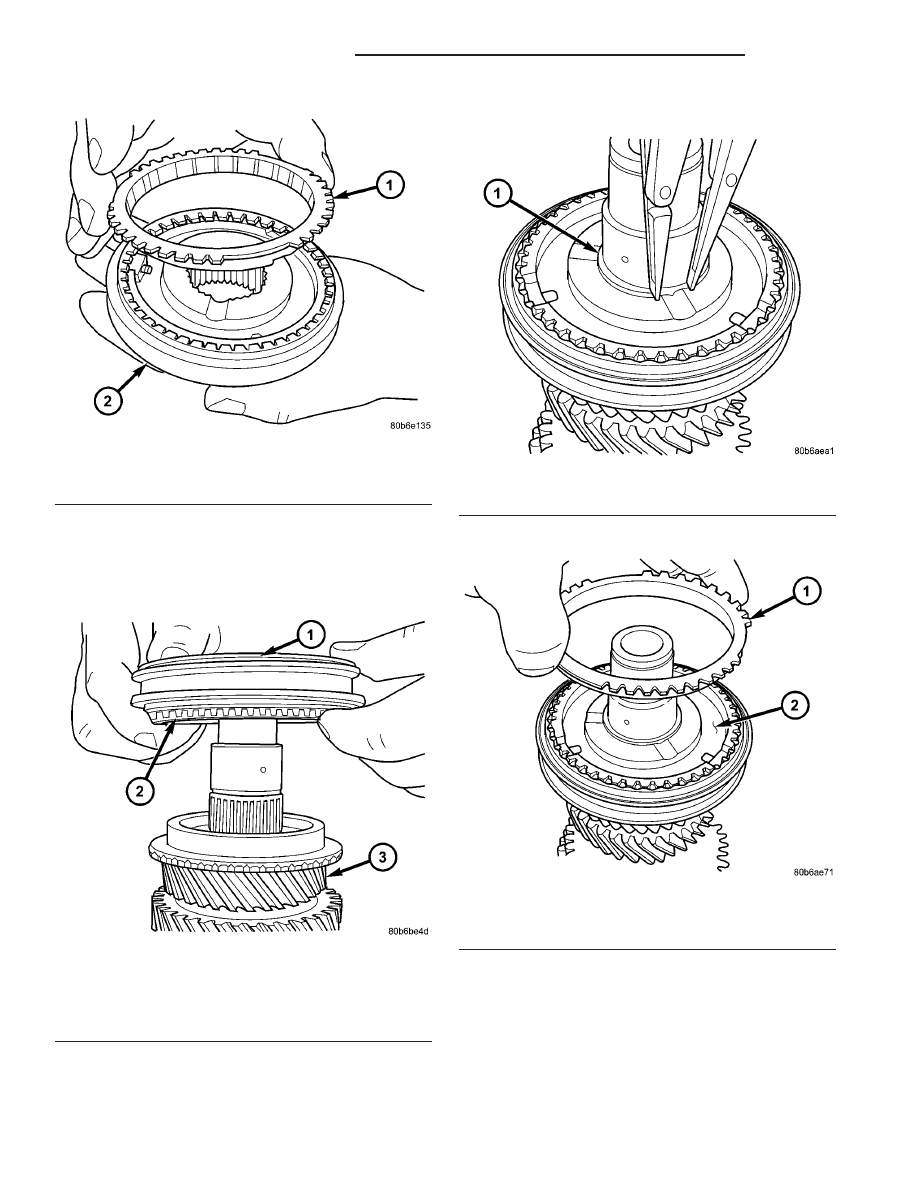
(17) Install 5th gear synchronizer assembly to

intermediate shaft (Fig. 202). When installing 5/R
synchronizer, make sure to align oil slots on
synchronizer hub face with oil hole in the shaft
splined hub journal.

(18) Install NEW 5/R synchro snap ring (Fig. 203).

(19) Install reverse gear blocker ring (Fig. 204).

Fig. 201 5th Gear Blocker Ring to Synchro

1 - 5th GEAR BLOCKER RING
2 - 5/R SYNCHRONIZER

Fig. 202 Install 5/R Synchro and 5th Blocker Ring to

5th Gear

1 - 5/R SYNCHRONIZER
2 - 5TH GEAR BLOCKER RING
3 - 5TH GEAR

Fig. 203 5/R Synchro Snap Ring

1 - SNAP RING

Fig. 204 Reverse Gear Blocker Ring

1 - REVERSE BLOCKER RING
2 - 5/R SYNCHRONIZER

21 - 128

T850 MANUAL TRANSAXLE

PL/SRT-4

INTERMEDIATE SHAFT (Continued)

(20) Install reverse gear needle bearing (Fig. 205).

(21) Install reverse gear to intermediate shaft.
(22) Install intermediate shaft sealed roller bear-

ing and thrust washer using installer 8482 (Fig. 206).

(23) Install NEW intermediate shaft sealed bear-

ing snap ring (Fig. 207).

SHIFT COVER

DESCRIPTION

The shift cover assembly (Fig. 208) (Fig. 209) is

operated by the gearshift crossover and selector
cables, and operates the shift fork/shaft system. It
consists of crossover and selector lever mechanisms,
transaxle vent, a main shift selector shaft, and the
5-R blockout mechanism. The shift cover is only ser-
viced as an assembly.

Fig. 205 Reverse Gear Needle Bearing

1 - NEEDLE BEARING

Fig. 206 Sealed Roller Bearing Installatiion

1 - ARBOR PRESS
2 - REMOVER/INSTALLER 8482
3 - SEALED ROLLER BEARING
4 - THRUST WASHER

Fig. 207 Intermediate Shaft Bearing Snap Ring

1 - SNAP RING
2 - BEARING

PL/SRT-4

T850 MANUAL TRANSAXLE

21 - 129

INTERMEDIATE SHAFT (Continued)

SHIFT FORK AND SHAFT

DESCRIPTION

The T850 utilizes a unique shift fork and shaft

arrangement consisting of three shift forks and two
shafts as shown in (Fig. 210). This system is oper-
ated by the shift cover assembly, which combined
with a unique gearshift cable design, offers a higher
mechanical advantage over traditional shift systems.
This arrangement results in less friction and lower
shift cable loads for smoother, more positive opera-
tion. The shift fork assemblies are constructed of
brass, float about the shafts with the aid of needle
bearings, and are serviced only as fork/bearing
assemblies.

Fig. 208 Shift Lever Identification

1 - SHIFT COVER ASSEMBLY
2 - VENT
3 - CROSSOVER LEVER
4 - SELECTOR LEVER

Fig. 209 Shift Cover Assembly Components

1 - SHAFT
2 - 5-R BLOCKOUT PIN/CAM
3 - SHIFT SELECTOR
4 - SHIFT BLOCKER
5 - SELECTOR LEVER/DETENT

Fig. 210 Shift Fork/Shaft Components

1 - 5/R FORK
2 - SHAFT/LINK ASSEMBLY
3 - LINK
4 - 3/4 FORK
5 - 1/2 FORK

21 - 130

T850 MANUAL TRANSAXLE

PL/SRT-4

SHIFT COVER (Continued)

SYNCHRONIZER

DESCRIPTION

The T850 transaxle uses two styles of synchronizer

assemblies; a conventional single-cone style is used
for the 5th/Reverse and 3rd/4th applications (Fig.
211), and a dual-cone style for the 1st/2nd gear appli-
cation (Fig. 212).

DISASSEMBLY

Place synchronizer in a clean shop towel and wrap.

Press on inner hub. Carefully open up shop towel
and remove springs, balls, keys, hub, and sleeve.

CLEANING

CLEAN

Do not attempt to clean the blocking rings in sol-

vent. The friction material will become contaminated.
Place synchronizer components in a suitable holder
and clean with solvent. Air dry.

INSPECTION

INSPECT

Proper inspection of components involve:
• Teeth, for wear, scuffed, nicked, burred, or bro-

ken teeth

• Keys, for wear or distortion

• Balls and springs, for distortion, cracks, or wear
If any of these conditions exist in these compo-

nents, replace as necessary.

ASSEMBLY

(1) Position synchronizer hub onto work bench.

Hub is non-directional.

(2) Install springs into hub slot.
(3) Insert key into hub and spring.
(4) Apply petroleum jelly to the hole in the key.

Insert balls into each key.

(5) Slide sleeve over the hub and depress balls as

you carefully slip the sleeve into position.

Fig. 211 3/4-5/R Synchronizer Assembly

1 - SLEEVE
2 - HUB
3 - BLOCKER RING (2)
4 - SPRING (3)
5 - KEY (3)
6 - BALL (3)

Fig. 212 1/2 Synchronizer Assembly

1 - SLEEVE
2 - REACTOR RING (2)
3 - HUB
4 - BLOCKER RING (2)
5 - SLEEVE
6 - FRICTION CONE (2)
7 - SPRING (3)
8 - KEY (3)
9 - BALL (3)

PL/SRT-4

T850 MANUAL TRANSAXLE

21 - 131


Content   ..  334  335  336  337   ..