Dodge Neon / Neon SRT-4. Manual - part 63
. . . . . . . . . . . . . . . . . . . . . . . . . 33
WATER PUMP INLET TUBE
. . . . . . . . . . . . . . . . . . . . . . . . . 34
. . . . . . . . . . . . . . . . . . . . . . . . . . . . . 34
. . . . . . . . . . . . . . . . . . . . . . . . . 34
ENGINE - 2.0L SOHC
DESCRIPTION - COOLING SYSTEM
The cooling system consists of an engine cooling
module, thermostat, coolant, a water pump to circu-
late the coolant. The engine cooling module may con-
sist of a radiator, electric fan motor, shroud, radiator
pressure cap, coolant reserve system, transmission
oil cooler and lines, hoses, clamps, and air condition-
ing condenser.
OPERATION
The primary purpose of a cooling system is to
maintain engine temperature in a range that will
provide satisfactory engine performance and emission
levels under all expected driving conditions. It also
provides hot water (coolant) for heater performance
and cooling for automatic transmission oil. It does
this by transferring heat from engine metal to cool-
ant, moving this heated coolant to the radiator, and
then transferring this heat to the ambient air.
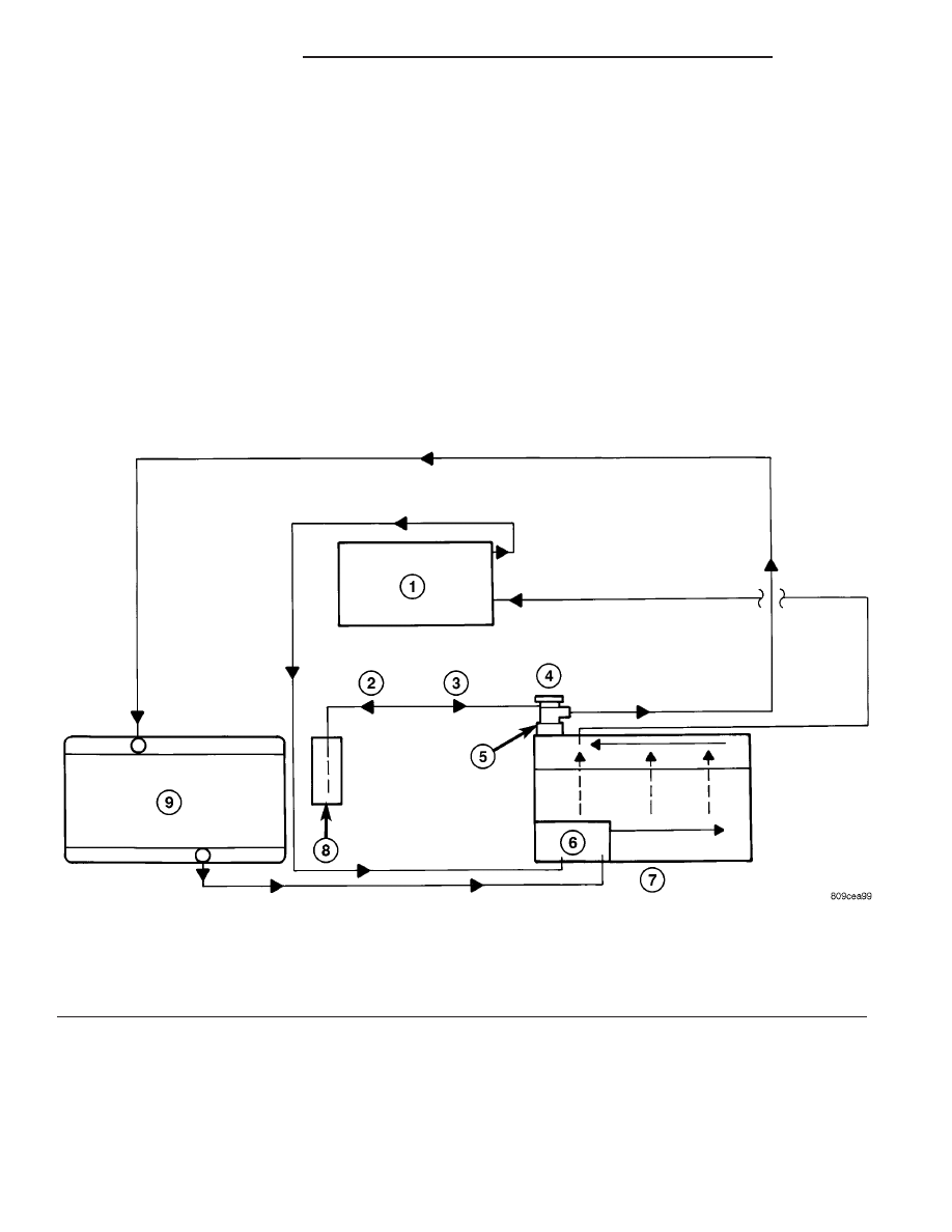
The coolant flow circuit is shown in (Fig. 1).
Fig. 1 Cooling System Operation
1 - HEATER
2 - HEAT UP
3 - COOL DOWN
4 - PRESSURE CAP
5 - THERMOSTAT HOUSING/COOLANT OUTLET
6 - WATER PUMP
7 - ENGINE
8 - COOLANT RECOVERY/RESERVE CONTAINER
9 - RADIATOR
7 - 10
ENGINE - 2.0L SOHC
PL/SRT-4