Dodge Caliber. Manual - part 988
P0621-GENERATOR LAMP/L-TERMINAL CONTROL CIRCUIT OPEN
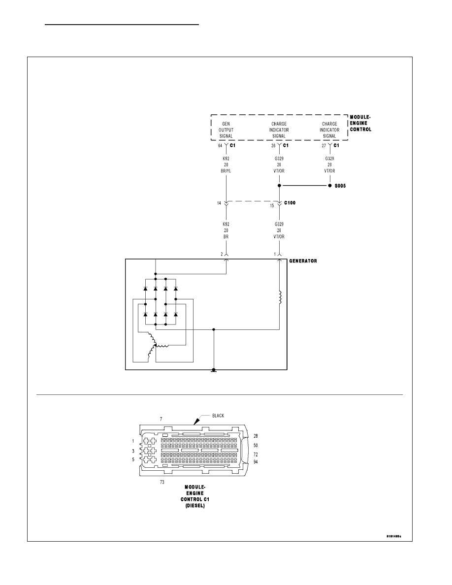
For a complete wiring diagram Refer to Section 8W
PM
ENGINE ELECTRICAL DIAGNOSTICS - DIESEL
9 - 1239
|
|
|
P0621-GENERATOR LAMP/L-TERMINAL CONTROL CIRCUIT OPEN For a complete wiring diagram Refer to Section 8W PM ENGINE ELECTRICAL DIAGNOSTICS - DIESEL 9 - 1239 |