Dodge Caliber. Manual - part 892


  Index      Dodge     Dodge Caliber - service repair manual 2007 year


Search            


Content   ..  890  891  892  893   ..


Dodge Caliber. Manual - part 892


3.

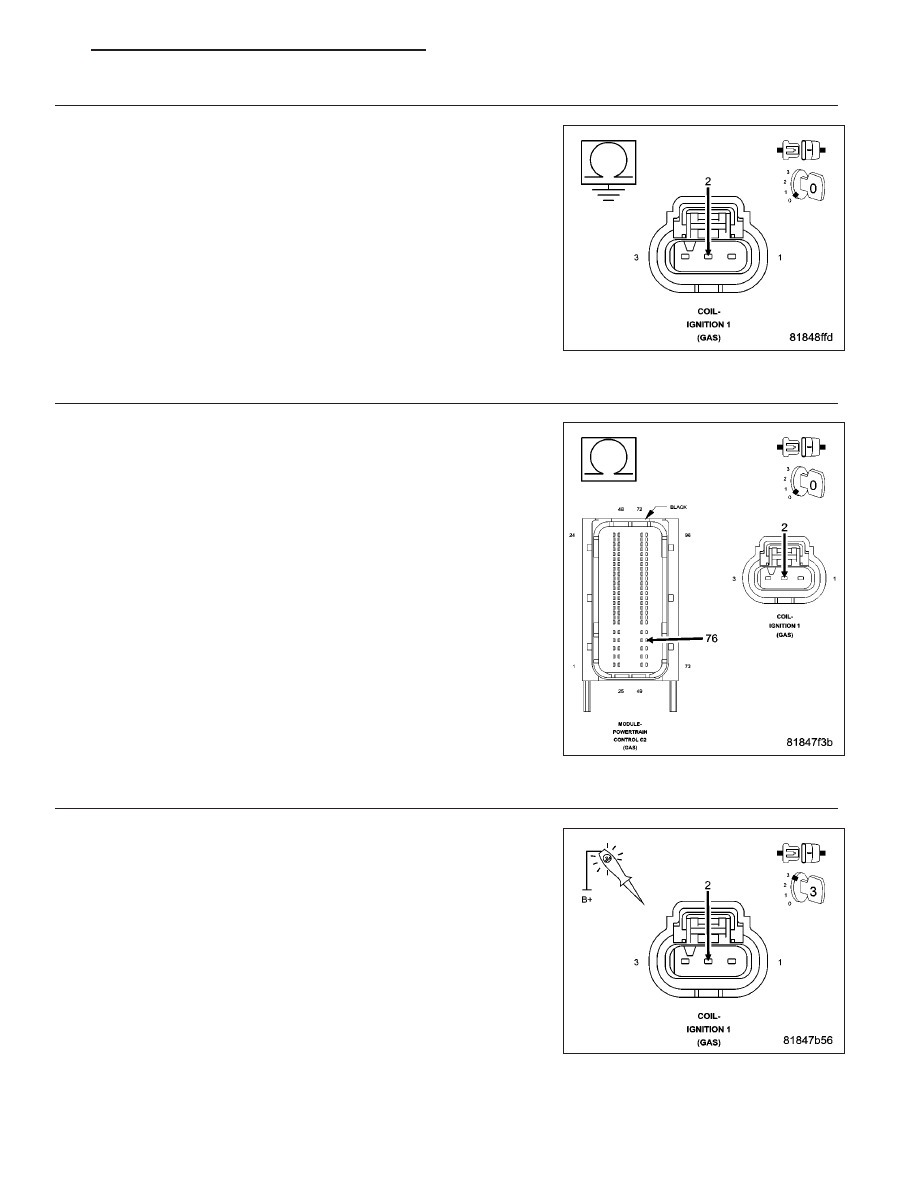
(K19) COIL 1 CONTROL CIRCUIT SHORTED TO GROUND

Turn the ignition off.

Disconnect the Powertrain Control Module (PCM) connector.

Measure the resistance between ground and the (K19) Coil 1 Control
circuit in the Ignition Coil 1 harness connector.

Is the resistance below 100 ohms?

Yes

>> Repair the (K19) Coil 1 Control circuit for a short to ground.

Perform the PCM Verification Test Ver. 1 (Refer to 9 -
ENGINE - DIAGNOSIS AND TESTING).

No

>> Go to 4

4.

(K19) COIL 1 CONTROL CIRCUIT OPEN OR HIGH RESISTANCE

Measure the resistance of the (K19) Coil 1 Control circuit between the
Ignition Coil 1 harness connector and the Powertrain Control Module
(PCM) harness connector.

Is the resistance below 5.0 ohms?

Yes

>> Go to 5

No

>> Repair the (K19) Coil 1 Control circuit for an open circuit or

high resistance.

Perform the PCM Verification Test Ver. 1 (Refer to 9 -
ENGINE - DIAGNOSIS AND TESTING).

5.

IGNITION COIL 1

WARNING: When the engine is operating, do not stand in direct
line with the fan. Do not put your hands near the pulleys, belts, or
fan. Do not wear loose clothing. Failure to follow these instruc-
tions can result in personal injury or death.
Connect the Powertrain Control Module (PCM) connector.

Using a 12 volt test light connected to 12 volts, check the (K19) Coil 1
Control circuit in the Ignition Coil 1 harness connector.

Crank the engine for 5 seconds.

NOTE: The test light should blink each time the circuit is activated
by the PCM.

Does the test light blink each time the circuit is activated by

PM

ENGINE ELECTRICAL DIAGNOSTICS - GPEC

9 - 855

the PCM?

Yes

>> Replace the Ignition Coil 1 in accordance with the Service Information.

Perform the PCM Verification Test Ver. 1 (Refer to 9 - ENGINE - DIAGNOSIS AND TESTING).

No

>> Go to 6

6.

POWERTRAIN CONTROL MODULE (PCM)

Using the wiring diagram/schematic as a guide, inspect the wiring and connectors between the Ignition Coil 1 and
the Powertrain Control Module (PCM).

Look for any chafed, pierced, pinched, or partially broken wires.

Look for broken, bent, pushed out or corroded terminals.

Refer to any Technical Service Bulletins that may apply.

Were any problems found?

Yes

>> Repair as necessary.

Perform the PCM Verification Test Ver. 1 (Refer to 9 - ENGINE - DIAGNOSIS AND TESTING).

No

>> Replace and program the Powertrain Control Module (PCM) in accordance with the Service Information.

Perform the PCM Verification Test Ver. 1 (Refer to 9 - ENGINE - DIAGNOSIS AND TESTING).

9 - 856

ENGINE ELECTRICAL DIAGNOSTICS - GPEC

PM

P2304-IGNITION COIL 2 CIRCUIT HIGH

For a complete wiring diagram Refer to Section 8W

PM

ENGINE ELECTRICAL DIAGNOSTICS - GPEC

9 - 857

When Monitored:
With the engine running and battery voltage greater than 10.4 volts.

Set Condition:
The Powertrain Control Module (PCM) detects that the (K17) Coil 2 Control circuit is shorted high.

Possible Causes

INTERMITTENT DTC

(K17) COIL 2 CONTROL CIRCUIT SHORTED TO VOLTAGE

(K17) COIL 2 CONTROL CIRCUIT SHORTED TO THE (K344) FUSED MAIN RELAY OUTPUT CIRCUIT

(K17) COIL 2 CONTROL CIRCUIT OPEN OR HIGH RESISTANCE

IGNITION COIL 2

POWERTRAIN CONTROL MODULE (PCM)

Always perform the Pre-Diagnostic Troubleshooting procedure before proceeding. (Refer to 9 - ENGINE -
DIAGNOSIS AND TESTING)

Diagnostic Test

1.

DTC IS ACTIVE

Ignition on, engine not running.

With the scan tool, Clear DTCs in the Powertrain Control Module (PCM).

Start the engine and allow it to reach normal operating temperature.

WARNING: When the engine is operating, do not stand in direct line with the fan. Do not put your hands
near the pulleys, belts, or fan. Do not wear loose clothing. Failure to follow these instructions can result in
personal injury or death.
With the scan tool, select View DTCs.

Is the status Active for this DTC?

Yes

>> Go to 2

No

>> Refer to the *CHECKING FOR AN INTERMITTENT DTC Diagnostic Procedure. (Refer to 9 - ENGINE -

DIAGNOSIS AND TESTING)

2.

(K17) COIL 2 CONTROL CIRCUIT SHORTED TO VOLTAGE

Turn the ignition off.

Disconnect the Ignition Coil 2 connector.

Disconnect the Powertrain Control Module (PCM) connector.

Turn the ignition on.

Measure the voltage of the (K17) Coil 2 Control circuit in the Ignition
Coil 2 harness connector.

Is there any voltage present?

Yes

>> Repair the (K17) Coil 2 Control circuit for a short to voltage.

Perform the PCM Verification Test Ver. 1 (Refer to 9 -
ENGINE - DIAGNOSIS AND TESTING).

No

>> Go to 3

9 - 858

ENGINE ELECTRICAL DIAGNOSTICS - GPEC

PM


Content   ..  890  891  892  893   ..