Dodge Caliber. Manual - part 799
3.
(B16) BRAKE SIGNAL 2 CIRCUIT
Turn the ignition on.
Using a 12 volt test light connected to ground, check the (B16) Brake
Signal 2 circuit in the Powertrain Control Module (PCM) harness con-
nector while pressing and releasing the brake pedal several times.
Does the test light change from illuminated when the pedal is
pressed to not illuminated when the pedal is released?
Yes
>> Go to 11
No
>> Go to 7
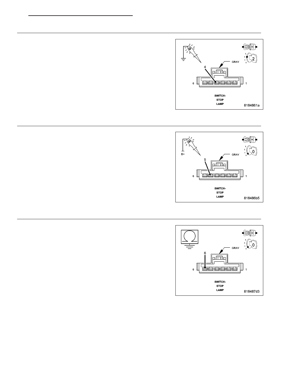
4.
(Z967) GROUND CIRCUIT OPEN OR HIGH RESISTANCE
Turn the ignition off.
Disconnect the Stop Lamp Switch connector.
Using a 12 volt test light connected to 12 volts, check the (Z967)
Ground circuit in the Stop Lamp Switch harness connector.
NOTE: The test light should be illuminated and bright. Compare
the brightness to that of a direct connection to the battery.
Is the test light illuminated and bright?
Yes
>> Go to 5
No
>> Repair the (Z967) Ground circuit for an open circuit or high
resistance.
Perform the PCM Verification Test Ver. 1 (Refer to 9 -
ENGINE - DIAGNOSIS AND TESTING).
5.
(B15) BRAKE SIGNAL 1 CIRCUIT SHORTED TO GROUND
Measure the resistance between ground and the (B15) Brake Signal 1
circuit in the Stop Lamp Switch harness connector.
Is the resistance above 100 ohms?
Yes
>> Go to 6
No
>> Repair the (B15) Brake Signal 1 circuit for a short to
ground.
Perform the PCM Verification Test Ver. 1 (Refer to 9 -
ENGINE - DIAGNOSIS AND TESTING).
PM
ENGINE ELECTRICAL DIAGNOSTICS - GPEC
9 - 483