Dodge Caliber. Manual - part 771


  Index      Dodge     Dodge Caliber - service repair manual 2007 year


Search            


Content   ..  769  770  771  772   ..


Dodge Caliber. Manual - part 771


10.

EVAPORATIVE EMISSION LEAK DETECTION

NOTE: A thorough visual inspection of the Evap system hoses, tubes, and connections may save time in
your diagnosis. Look for any physical damage or signs of wetness at connections. The strong smell of fuel
vapors may aid diagnosis also.
Remove the Air supply hose from the service port or the #8404-ADP adapter.

Connect the SMOKE supply tip (black hose) to the service port (if equipped) or to the #8404-ADP adapter.

Set the smoke/air control switch to SMOKE.

NOTE: The flow meter indicator ball will not move at this point.
Press the remote smoke/air start button.

NOTE: Make sure that smoke has filled the EVAP system by continuing to press the remote smoke/air start
button, remove the vehicle fuel cap, and wait for the smoke to exit. Once smoke is indicated reinstall the
fuel cap.

NOTE: For optimal performance, introduce smoke into the system for an additional 60 seconds; continue
introducing smoke at 15 second intervals, as necessary.
While still holding the remote smoke/air start button, use the white light (#8404-CLL) to follow the EVAP system
path, and look for the source of the leak indicated by exiting smoke.

If a leak is concealed from view (i.e., top of fuel tank), release the remote smoke/air start button, and use the ultra-
violet (UV) black light #8404-UVL and the yellow goggles 8404-20 to look for residual traces of dye that are left
behind by the smoke.

The exiting smoke deposits a residual fluid that is either bright green or bright yellow when viewed with a UV light.

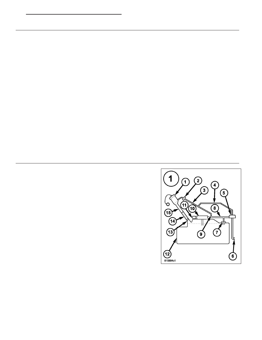
NOTE: The EVAP System is divided into three zones. A leak from any of these zones can cause this DTC to
set. The lists below specify the possible leak points in the specific zones. For further assistance see the
Zone Identification Charts below.

— ZONE 1—

1 Fuel Cap

2 Recirculation Check Valve.

3 Vapor Recirculation Line.

4 Signal Vapor Line for FVM.

5 Flow Management Valve.

6 Fuel Tank to Canister Vapor Line.

7 Fuel Tank Vent (Check Valve).

8 Vapor Line to Canister.

9 Flow Control Orifice.

10 Control Valve.

11 Liquid Trap.

12 Fuel Tank.

13 Check valve.

14 Fuel Fill Tube to Tank connector.

15 Fuel Fill Tube

Damaged or disconnected components.

— ZONE 2 —

1 Filter.

2 ESM.

3 Canister Vent Line.

4 Evap Canister.

5 Chassis Purge Valve.

6 Fuel Tank to Canister Vapor Line connection.

7 Evap Purge connection.

— ZONE 3 —

1 Evap Purge Vacuum Line.

PM

ENGINE ELECTRICAL DIAGNOSTICS - GPEC

9 - 371

2 Connection to Chassis Line.

3 Connection to Canister.

4 Chassis Purge Line.

5 Evap Purge Vacuum Line.

6 Connection to Evap Purge Harness.

7 Chassis Evap Purge Line connection to Engine Vacuum.

8 Evap Purge Valve.

9 Service Port.

NOTE: Carefully inspect the vent side of the EVAP Canister. Due to
the filtering system in the canister the smoke or dye may or may
not be visible. Introducing smoke into the filtered side of the can-
ister may assist in locating the leak.

Was a leak found?

Yes

>> Repair or replace the leaking component as necessary.

Perform the PCM Verification Test Ver. 1 (Refer to 9 -
ENGINE - DIAGNOSIS AND TESTING).

No

>> Go to 11

9 - 372

ENGINE ELECTRICAL DIAGNOSTICS - GPEC

PM

11.

EVAP PURGE HOSE/TUBE OBSTRUCTION

Inspect the Evap Purge hose/tube for proper routing and installation between the EVAP Purge Solenoid and the
Fuel Tank and between the Fuel Tank and the Evap Purge Canister.

Make sure the hose/tube is not damaged or kinked and is free from any obstructions or blockage.

Were any problems found?

Yes

>> Repair or replace as necessary.

Perform the PCM Verification Test Ver. 1 (Refer to 9 - ENGINE - DIAGNOSIS AND TESTING).

No

>> Go to 12

12.

EVAP SYSTEM MONITOR SWITCH

Using the wiring diagram/schematic as a guide, inspect the wiring and connectors between the Evap System Mon-
itor Switch and the Powertrain Control Module (PCM).

Look for any chafed, pierced, pinched, or partially broken wires.

Look for broken, bent, pushed out or corroded terminals.

Refer to any Technical Service Bulletins that may apply.

Were any problems found?

Yes

>> Repair as necessary.

Perform the PCM Verification Test Ver. 1 (Refer to 9 - ENGINE - DIAGNOSIS AND TESTING).

No

>> Replace the Evap System Monitor Switch in accordance with the Service Information.

Perform the PCM Verification Test Ver. 1 (Refer to 9 - ENGINE - DIAGNOSIS AND TESTING).

13.

POWERTRAIN CONTROL MODULE (PCM)

Using the wiring diagram/schematic as a guide, inspect the wiring and connectors between the Evap System Mon-
itor Switch and the Powertrain Control Module (PCM).

Look for any chafed, pierced, pinched, or partially broken wires.

Look for broken, bent, pushed out or corroded terminals.

Refer to any Technical Service Bulletins that may apply.

Were any problems found?

Yes

>> Repair as necessary.

Perform the PCM Verification Test Ver. 1 (Refer to 9 - ENGINE - DIAGNOSIS AND TESTING).

No

>> Replace and program the Powertrain Control Module (PCM) in accordance with the Service Information.

Perform the PCM Verification Test Ver. 1 (Refer to 9 - ENGINE - DIAGNOSIS AND TESTING).

PM

ENGINE ELECTRICAL DIAGNOSTICS - GPEC

9 - 373

P0441-EVAP PURGE SYSTEM PERFORMANCE

For a complete wiring diagram Refer to Section 8W.

9 - 374

ENGINE ELECTRICAL DIAGNOSTICS - GPEC

PM


Content   ..  769  770  771  772   ..