Dodge Caliber. Manual - part 765


  Index      Dodge     Dodge Caliber - service repair manual 2007 year


Search            


Content   ..  763  764  765  766   ..


Dodge Caliber. Manual - part 765


5.

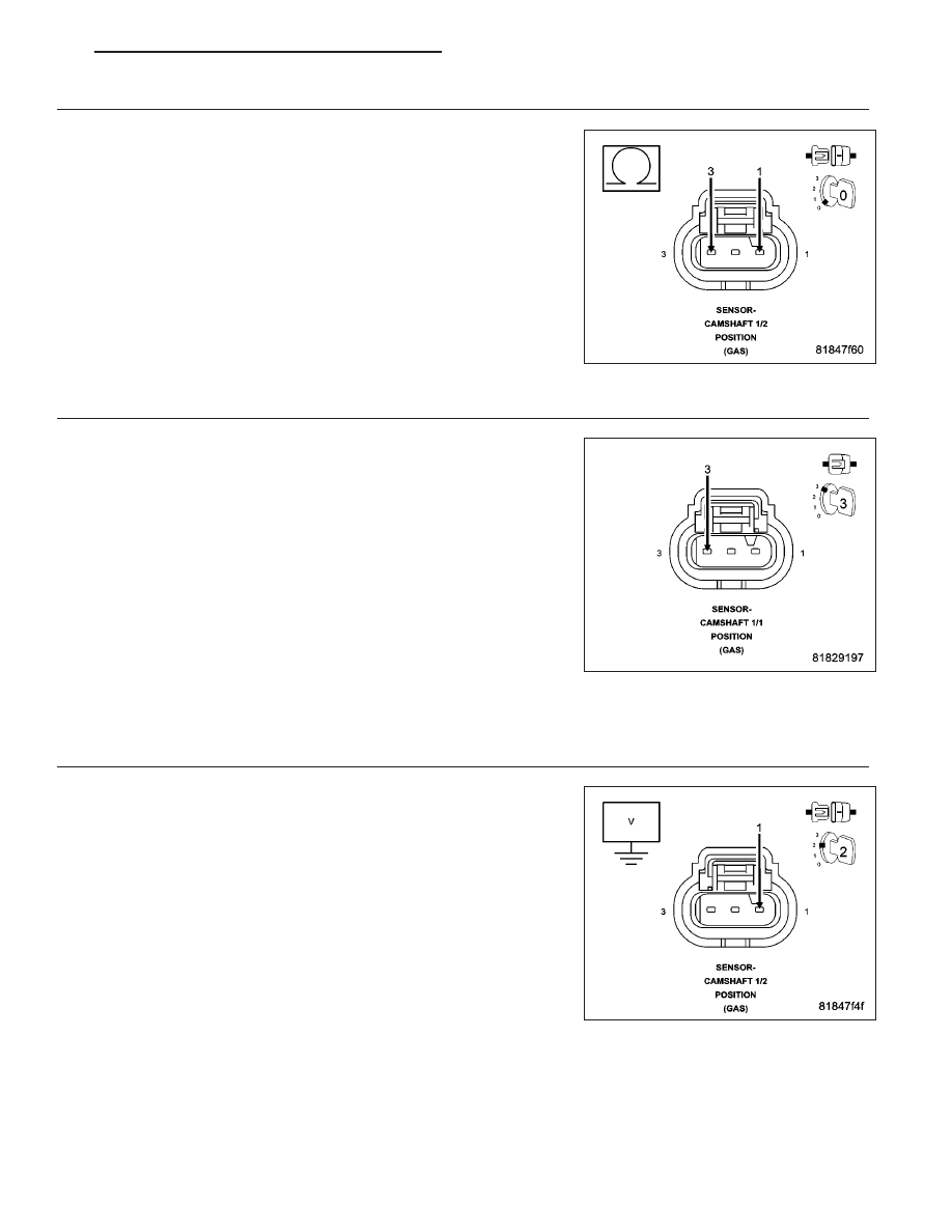
(F855) 5 VOLT SUPPLY CIRCUIT SHORTED TO THE (K441) CMP 1/2 SIGNAL CIRCUIT

Measure the resistance between the (F855) 5 Volt Supply circuit and
the (K441) CMP 1/2 Signal circuit in the Camshaft 1/2 Position Sensor
harness connector.

Is the resistance above 100 ohms?

Yes

>> Go to 6

No

>> Repair the (F855) 5 Volt Supply circuit for a short to the

(K441) CMP 1/2 Signal circuit.

Perform the PCM Verification Test Ver. 1 (Refer to 9 -
ENGINE - DIAGNOSIS AND TESTING).

6.

CAMSHAFT 1/1 POSITION SENSOR IRREGULAR SIGNAL

Connect the Camshaft 1/2 Position Sensor connector.

Using a lab scope and the Miller special tool #6801, backprobe the
(K44) CMP 1/1 Signal circuit in the Camshaft 1/1 Position Sensor har-
ness connector.

Ignition on, engine not running.

Wiggle the related wire harness and lightly tap on the Camshaft 1/1
Position Sensor while monitoring the lab scope screen.

Start the engine.

Monitor the Camshaft 1/1 Position Sensor signal on the lab scope
screen.

Were any Camshaft 1/1 Position Sensor signals irregular or
missing?

Yes

>> Go to 16

No

>> Go to 17

7.

(F855) 5 VOLT SUPPLY CIRCUIT SHORTED TO VOLTAGE

Turn the ignition off.

Disconnect the Powertrain Control Module (PCM) connector.

Turn the ignition on.

Measure the voltage of the (F855) 5 Volt Supply circuit in the Camshaft
1/2 Position Sensor harness connector.

Is there any voltage present?

Yes

>> Repair the (F855) 5 Volt Supply circuit for a short to volt-

age.

Perform the PCM Verification Test Ver. 1 (Refer to 9 -
ENGINE - DIAGNOSIS AND TESTING).

No

>> Go to 8

PM

ENGINE ELECTRICAL DIAGNOSTICS - GPEC

9 - 347

8.

(F855) 5 VOLT SUPPLY CIRCUIT SHORTED TO GROUND

Turn the ignition off.

Measure the resistance between ground and the (F855) 5 Volt Supply
circuit in the Camshaft 1/2 Position Sensor harness connector.

Is the resistance above 100 ohms?

Yes

>> Go to 9

No

>> Repair the (F855) 5 Volt Supply circuit for a short to ground.

Perform the PCM Verification Test Ver. 1 (Refer to 9 -
ENGINE - DIAGNOSIS AND TESTING).

9.

(F855) 5 VOLT SUPPLY CIRCUIT SHORTED TO THE (K915) SENSOR GROUND CIRCUIT

Measure the resistance between the (F855) 5 Volt Supply circuit and
the (K915) Sensor Ground circuit in the Camshaft 1/2 Position Sensor
harness connector.

Is the resistance above 100 ohms?

Yes

>> Go to 10

No

>> Repair the (F855) 5 Volt Supply circuit for a short to the

(K915) Sensor Ground circuit.

Perform the PCM Verification Test Ver. 1 (Refer to 9 -
ENGINE - DIAGNOSIS AND TESTING).

10.

(F855) 5 VOLT SUPPLY CIRCUIT OPEN OR HIGH RESISTANCE

Measure the resistance of the (F855) 5 Volt Supply circuit between the
Camshaft 1/2 Position Sensor harness connector and the Powertrain
Control Module (PCM) harness connector.

Is the resistance below 5.0 ohms?

Yes

>> Go to 18

No

>> Repair the (F855) 5 Volt Supply circuit for an open circuit or

high resistance.

Perform the PCM Verification Test Ver. 1 (Refer to 9 -
ENGINE - DIAGNOSIS AND TESTING).

9 - 348

ENGINE ELECTRICAL DIAGNOSTICS - GPEC

PM

11.

(K441) CMP 1/2 SIGNAL CIRCUIT SHORTED TO VOLTAGE

Turn the ignition off.

Disconnect the Powertrain Control Module (PCM) connector.

Turn the ignition on.

Measure the voltage of the (K441) CMP 1/2 Signal circuit in the Cam-
shaft 1/2 Position Sensor harness connector.

Is there any voltage present?

Yes

>> Repair the (K441) CMP 1/2 Signal circuit for a short to volt-

age.

Perform the PCM Verification Test Ver. 1 (Refer to 9 -
ENGINE - DIAGNOSIS AND TESTING).

No

>> Go to 12

12.

(K441) CMP 1/2 SIGNAL CIRCUIT SHORTED TO GROUND

Turn the ignition off.

Measure the resistance between ground and the (K441) CMP 1/2 Sig-
nal circuit in the Camshaft 1/2 Position Sensor harness connector.

Is the resistance above 100 ohms?

Yes

>> Go to 13

No

>> Repair the (K441) CMP 1/2 Signal circuit for a short to

ground.

Perform the PCM Verification Test Ver. 1 (Refer to 9 -
ENGINE - DIAGNOSIS AND TESTING).

13.

(K441) CMP 1/2 SIGNAL CIRCUIT SHORTED TO (K915) SENSOR GROUND CIRCUIT

Measure the resistance between the (K441) CMP 1/2 Signal circuit and
the (K915) Sensor Ground circuit in the Camshaft 1/2 Position Sensor
harness connector.

Is the resistance above 100 ohms?

Yes

>> Go to 14

No

>> Repair the (K441) CMP 1/2 Signal circuit for a short to the

(K915) Sensor Ground circuit.

Perform the PCM Verification Test Ver. 1 (Refer to 9 -
ENGINE - DIAGNOSIS AND TESTING).

PM

ENGINE ELECTRICAL DIAGNOSTICS - GPEC

9 - 349

14.

(K441) CMP 1/2 SIGNAL CIRCUIT OPEN OR HIGH RESISTANCE

Measure the resistance of the (K441) CMP 1/2 Signal circuit between
the Camshaft 1/2 Position Sensor harness connector and the Power-
train Control Module (PCM) harness connector.

Is the resistance below 5.0 ohms?

Yes

>> Go to 18

No

>> Repair the (K441) CMP 1/2 Signal circuit for an open circuit

or high resistance.

Perform the PCM Verification Test Ver. 1 (Refer to 9 -
ENGINE - DIAGNOSIS AND TESTING).

15.

(K915) SENSOR GROUND CIRCUIT OPEN OR HIGH RESISTANCE

Turn the ignition off.

Disconnect the Powertrain Control Module (PCM) connector.

Measure the resistance of the (K915) Sensor Ground circuit between
the Camshaft 1/2 Position Sensor harness connector and the Power-
train Control Module (PCM) harness connector.

Is the resistance below 5.0 ohms?

Yes

>> Go to 18

No

>> Repair the circuit for an (K915) Sensor Ground open circuit

or high resistance.

Perform the PCM Verification Test Ver. 1 (Refer to 9 -
ENGINE - DIAGNOSIS AND TESTING).

9 - 350

ENGINE ELECTRICAL DIAGNOSTICS - GPEC

PM


Content   ..  763  764  765  766   ..