Dodge Caliber. Manual - part 719
5.
(K141) O2 1/2 SIGNAL CIRCUIT SHORTED TO GROUND
Turn the ignition off.
Measure the resistance between ground and the (K141) O2 1/2 Signal
circuit in the Oxygen Sensor 1/2 harness connector.
Is the resistance below 100 ohms?
Yes
>> Repair the (K141) O2 1/2 Signal circuit for a short to
ground.
Perform the PCM Verification Test Ver. 1 (Refer to 9 -
ENGINE - DIAGNOSIS AND TESTING).
No
>> Go to 6
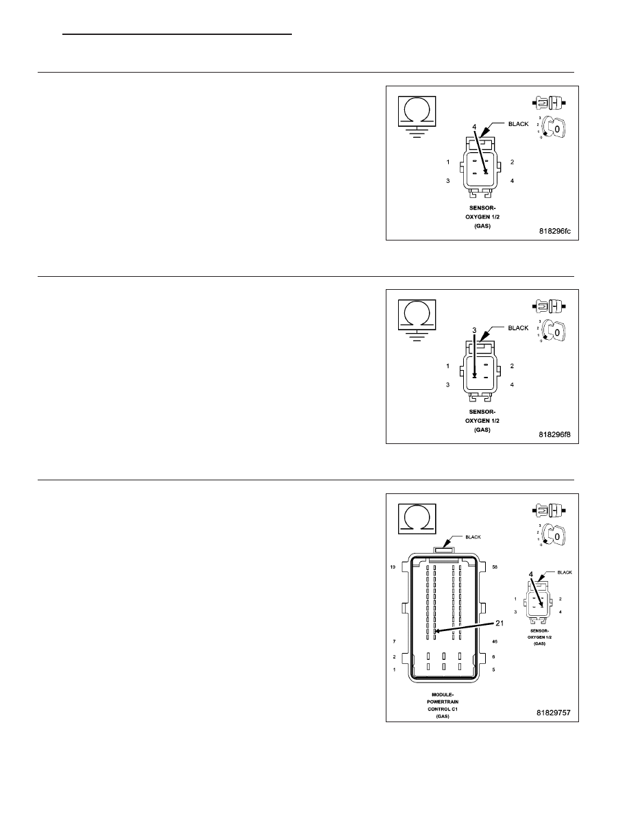
6.
(K904) O2 1/2 RETURN CIRCUIT SHORTED TO GROUND
Measure the resistance between ground and the (K904) O2 1/2 Return
circuit in the Oxygen Sensor 1/2 harness connector.
Is the resistance below 100 ohms?
Yes
>> Repair the (K904) O2 1/2 Return circuit for a short to
ground.
Perform the PCM Verification Test Ver. 1 (Refer to 9 -
ENGINE - DIAGNOSIS AND TESTING).
No
>> Go to 7
7.
(K141) O2 1/2 SIGNAL CIRCUIT OPEN OR HIGH RESISTANCE
Measure the resistance of the (K141) O2 1/2 Signal circuit between the
Oxygen Sensor 1/2 harness connector to the Powertrain Control Module
(PCM) harness connector.
Is the resistance below 5.0 ohms?
Yes
>> Go to 8
No
>> Repair the (K141) O2 1/2 Signal circuit for an open circuit
or high resistance.
Perform the PCM Verification Test Ver. 1 (Refer to 9 -
ENGINE - DIAGNOSIS AND TESTING).
PM
ENGINE ELECTRICAL DIAGNOSTICS - GPEC
9 - 163