Dodge Caliber. Manual - part 685


  Index      Dodge     Dodge Caliber - service repair manual 2007 year


Search            


Content   ..  683  684  685  686   ..


Dodge Caliber. Manual - part 685


2.

ENGINE OIL DIRTY OR CONTAMINATED

Turn the ignition off.

Inspect engine oil for signs of contamination, sludge, or foreign material.

Were any problems found?

Yes

>> Clean the engine oil system, including oil passages and, if necessary, replace the Oil Control Valve inlet

screen(s), in accordance with the Service Information.

Perform the PCM Verification Test Ver. 1 (Refer to 9 - ENGINE - DIAGNOSIS AND TESTING).

No

>> Go to 3

3.

INCORRECT ENGINE OIL VISCOSITY

Review service history to determine if the correct viscosity engine oil was used.

Were any problems found?

Yes

>> Change the engine oil in accordance with the Service Information and retest.

Perform the PCM Verification Test Ver. 1 (Refer to 9 - ENGINE - DIAGNOSIS AND TESTING).

No

>> Go to 4

4.

CAMSHAFT 1/2 POSITION SOLENOID CONTROL ACTUATION

Turn the ignition on.

With the scan tool, actuate the Camshaft 1/2 Position Solenoid control to toggle on and off.

Listen for the Camshaft 1/2 Position Solenoid to click open and closed during the actuation.

Does the Camshaft 1/2 Position Solenoid click open and closed during the actuation?

Yes

>> Go to 8

No

>> Go to 5

5.

(K343) FUSED MAIN RELAY OUTPUT CIRCUIT HIGH RESISTANCE

Turn the ignition off.

Disconnect the Camshaft 1/2 Position Solenoid connector.

Turn the ignition on.

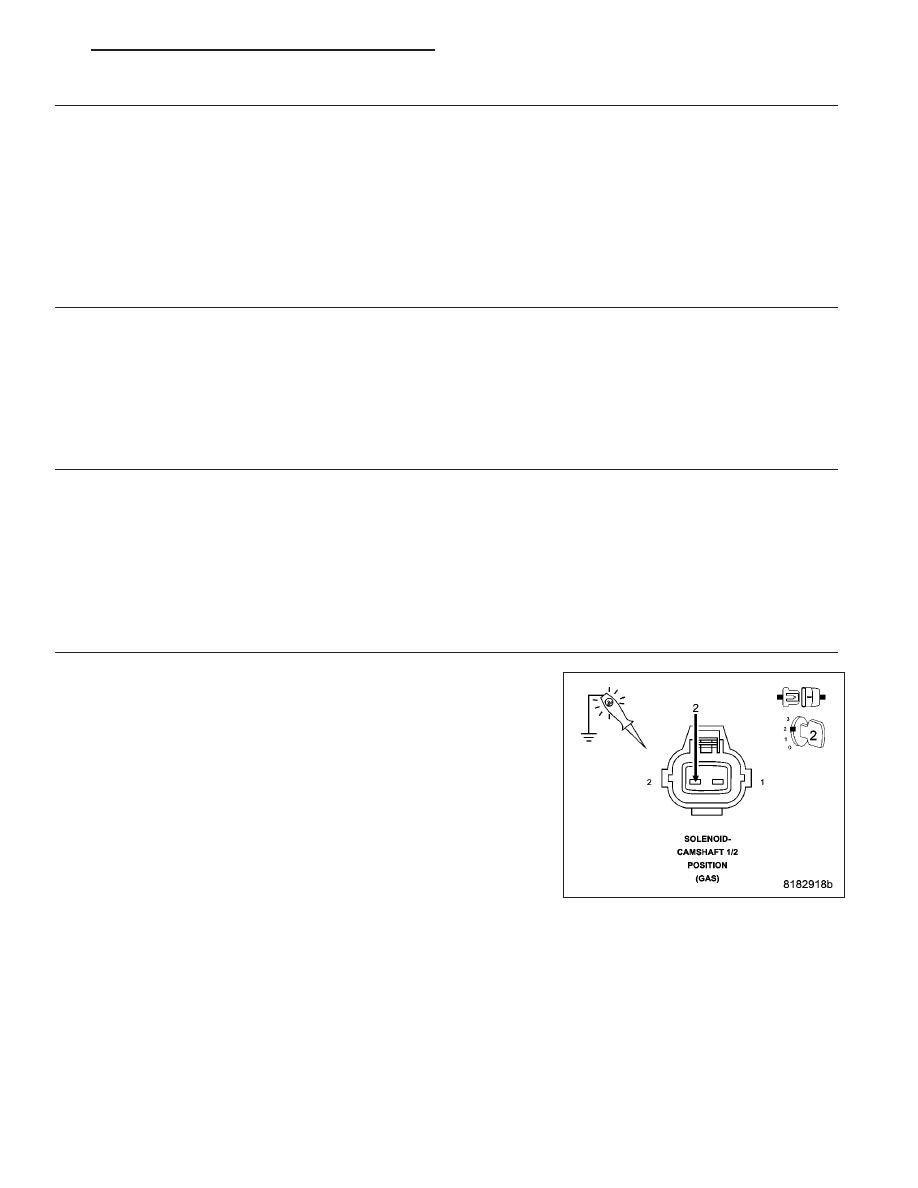
Using a 12 volt test light connected to ground, check the (K343) Fused
Main Relay Output circuit in the Camshaft 1/2 Position Solenoid har-
ness connector.

NOTE: The test light should be illuminated and bright. Compare
the brightness to that of a direct connection to the battery.

Is the test light illuminated and bright?

Yes

>> Go to 6

No

>> Repair the (K343) Fused Main Relay Output circuit for high

resistance.

Perform the PCM Verification Test Ver. 1 (Refer to 9 - ENGINE - DIAGNOSIS AND TESTING).

PM

ENGINE ELECTRICAL DIAGNOSTICS - GPEC

9 - 27

6.

(K276) CMP 1/2 CONTROL CIRCUIT HIGH RESISTANCE

With the scan tool, actuate the Camshaft 1/2 Position Solenoid control
to the ON (100%) position.

Using a 12 volt test light connected to 12 volts, check the (K276) CMP
1/2 Control circuit in the Camshaft 1/2 Position Solenoid harness con-
nector.

NOTE: The test light should be illuminated and bright. Compare
the brightness to that of a direct connection to the battery.

Is the test light illuminated and bright?

Yes

>> Go to 7

No

>> Repair the (K276) CMP 1/2 Control circuit for high resis-

tance.

Perform the PCM Verification Test Ver. 1 (Refer to 9 -
ENGINE - DIAGNOSIS AND TESTING).

7.

CAMSHAFT 1/2 POSITION SOLENOID

Turn the ignition off.

Inspect the wiring and connectors between the Camshaft 1/2 Position Solenoid and the Powertrain Control Module
(PCM).

Look for any chafed, pierced, pinched, or partially broken wires.

Look for broken, bent, pushed out or corroded terminals.

Remove the Camshaft 1/2 Position Solenoid in accordance with the Service Information.

Inspect the Camshaft 1/2 Position Solenoid for contamination, foreign material, or any condition that would restrict
movement of the valve.

Were any problems found?

Yes

>> Repair as necessary.

Perform the PCM Verification Test Ver. 1 (Refer to 9 - ENGINE - DIAGNOSIS AND TESTING).

No

>> Replace the Camshaft 1/2 Position Solenoid in accordance with the Service Information.

Perform the PCM Verification Test Ver. 1 (Refer to 9 - ENGINE - DIAGNOSIS AND TESTING).

8.

CAMSHAFT PHASER

Turn the ignition off.

Remove the appropriate Camshaft Phaser in accordance with the Service information.

Inspect the Phaser for contamination, foreign material, or any condition that would restrict operation of the Phaser.

Inspect the Phaser oil passages for signs of sludge or foreign material.

Were any problems found?

Yes

>> Repair as necessary.

Perform the PCM Verification Test Ver. 1 (Refer to 9 - ENGINE - DIAGNOSIS AND TESTING).

No

>> Replace the appropriate Camshaft Phaser in accordance with the Service Information.

Perform the PCM Verification Test Ver. 1 (Refer to 9 - ENGINE - DIAGNOSIS AND TESTING).

9 - 28

ENGINE ELECTRICAL DIAGNOSTICS - GPEC

PM

P0016-CRANKSHAFT-CAMSHAFT TIMING MISALIGNMENT-BANK 1 SENSOR 1

For a complete wiring diagram Refer to Section 8W.

PM

ENGINE ELECTRICAL DIAGNOSTICS - GPEC

9 - 29

When Monitored:
With the engine speed present and within a calibrated amount.

Set Condition:
The PCM detects that the camshaft position is out of phase with the crankshaft position. One Trip Fault. Three
good trips to turn off the MIL.

Possible Causes

CRANKSHAFT POSITION SENSOR CIRCUIT WIRING OR CONNECTORS

CAMSHAFT 1/1 POSITION SENSOR CIRCUIT WIRING OR CONNECTORS

CRANKSHAFT POSITION SENSOR

CAMSHAFT 1/1 POSITION SENSOR

CRANKSHAFT, TONE WHEEL OR FLEX PLATE

CAMSHAFT, TONE WHEEL OR PULSE RING

Always perform the Pre-Diagnostic Troubleshooting procedure before proceeding. (Refer to 9 - ENGINE -
DIAGNOSIS AND TESTING).

Diagnostic Test

1.

DTC IS ACTIVE

Ignition on, engine not running.

With the scan tool select View DTCs.

Record the related Freeze Frame data.

Start the engine and allow it to reach operating temperature.

WARNING: When the engine is operating, do not stand in direct line with the fan. Do not put your hands
near the pulleys, belts, or fan. Do not wear loose clothing. Failure to follow these instructions can result in
personal injury or death.

NOTE: If the DTC does not reset it may be necessary to test drive the vehicle.

Is the status Active for this DTC?

Yes

>> Go to 2

No

>> Refer to the *CHECKING FOR AN INTERMITTENT DTC Diagnostic Procedure. (Refer to 9 - ENGINE -

DIAGNOSIS AND TESTING)

2.

CRANKSHAFT POSITION SENSOR CIRCUIT WIRING OR CONNECTORS

Turn the ignition off.

Using the wiring diagram/schematic as a guide, inspect the wiring and connectors between the Crankshaft Position
Sensor and the Powertrain Control Module (PCM).

Look for any chafed, pierced, pinched, or partially broken wires.

Look for broken, bent, pushed out or corroded terminals.

Inspect the Crankshaft Position Sensor for conditions such as loose mounting screws, damage, or cracks.

Were any problems found?

Yes

>> Repair as necessary.

Perform the PCM Verification Test Ver. 1 (Refer to 9 - ENGINE - DIAGNOSIS AND TESTING).

No

>> Go to 3

9 - 30

ENGINE ELECTRICAL DIAGNOSTICS - GPEC

PM


Content   ..  683  684  685  686   ..