Dodge Caliber. Manual - part 566


  Index      Dodge     Dodge Caliber - service repair manual 2007 year


Search            


Content   ..  564  565  566  567   ..


Dodge Caliber. Manual - part 566


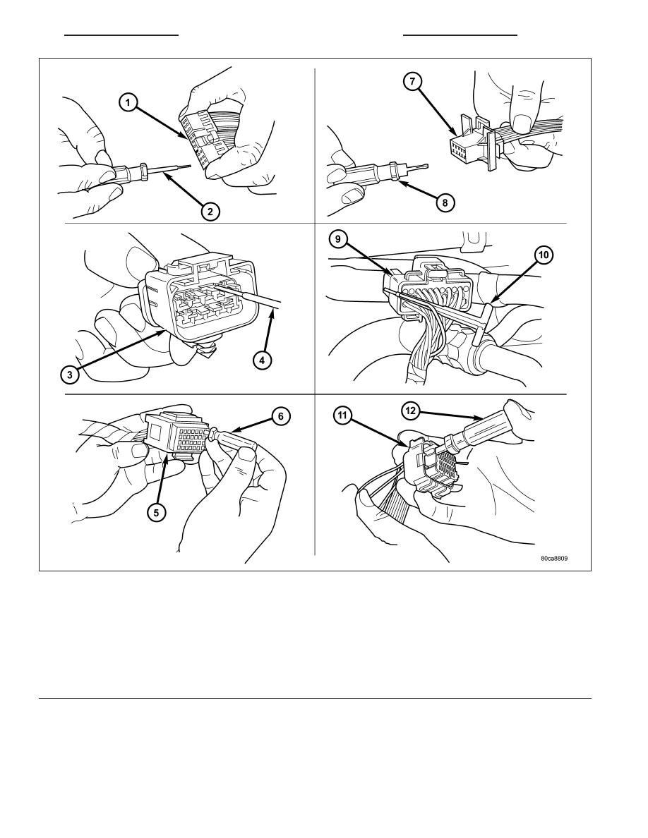
6. Position the connector locking finger away from the terminal using the proper special tool. Pull on the wire to

remove the terminal from the connector.

1 - TYPICAL CONNECTOR
2 - PICK FROM SPECIAL TOOL KIT 6680
3 - APEX CONNECTOR
4 - PICK FROM SPECIAL TOOL KIT 6680
5 - AUGAT CONNECTOR
6 - SPECIAL TOOL 6932
7 - MOLEX CONNECTOR
8 - SPECIAL TOOL 6742
9 - THOMAS AND BETTS CONNECTOR
10 - SPECIAL TOOL 6934
11 - TYCO CONNECTOR
12 - SPECIAL TOOL 8638

PM

8W-01 WIRING DIAGRAM INFORMATION

8W - 01 - 17

INSTALLATION

1. Insert the removed terminal in the same cavity on the repair connector.

2. Repeat steps for each terminal in the connector, being sure that all wires are inserted into the proper cavities.

For additional connector pin-out identification, refer to the wiring diagrams.

3. When the connector is re-assembled, the secondary terminal lock must be placed in the locked position to pre-

vent terminal push out.

4. Replace dress cover (if applicable).

5. Connect connector to its mating half/component.

6. Connect battery and test all affected systems.

8W - 01 - 18

8W-01 WIRING DIAGRAM INFORMATION

PM

DIODE

REMOVAL

1. Disconnect the battery.

2. Locate the diode in the harness, and remove the

protective covering.

3. Remove the diode from the harness, pay attention

to the current flow direction (1) (2) (3).

INSTALLATION

1. Remove the insulation from the wires in the harness. Only remove enough insulation to solder in the new diode.

2. Install the new diode in the harness, making sure current flow is correct. If necessary, refer to the appropriate

wiring diagram for current flow.

3. Solder the connection together using rosin core type solder only. Do not use acid core solder.

4. Tape the diode to the harness using electrical tape. Make sure the diode is completely sealed from the elements.

5. Re-connect the battery and test affected systems.

PM

8W-01 WIRING DIAGRAM INFORMATION

8W - 01 - 19

TERMINAL

REMOVAL

1. Follow steps for removing terminals described in the connector removal section.

2. Cut the wire 6 inches from the back of the connector.

INSTALLATION

1. Select a wire from the terminal repair kit that best matches the color and gage of the wire being repaired.

2. Cut the repair wire to the proper length and remove one–half (1/2) inch of insulation.

3. Splice the repair wire to the wire harness (see wire splicing procedure) (Refer to 8 - ELECTRICAL/WIRING DIA-

GRAM INFORMATION/WIRE - STANDARD PROCEDURE).

4. Insert the repaired wire into the connector.

5. Install the connector locking wedge, if required, and reconnect the connector to its mating half/component.

6. Re-tape the wire harness starting at 1–1/2 inches behind the connector and 2 inches past the repair.

7. Connect battery and test all affected systems.

8W - 01 - 20

8W-01 WIRING DIAGRAM INFORMATION

PM


Content   ..  564  565  566  567   ..