Dodge Caliber. Manual - part 512


  Index      Dodge     Dodge Caliber - service repair manual 2007 year


Search            


Content   ..  510  511  512  513   ..


Dodge Caliber. Manual - part 512


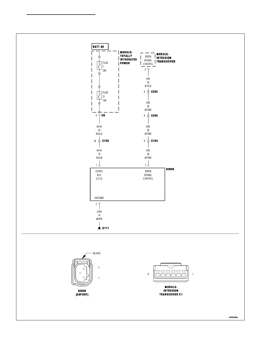
U1416-IMPLAUSIBLE SECURITY SIREN SIGNAL RECEIVED

For a complete wiring diagram Refer to Section 8W.

PM

VEHICLE THEFT SECURITY - ELECTRICAL DIAGNOSTICS

8Q - 25

When Monitored:
Continuously while the VTSS is armed.

Set Condition:
If the Intrusion Transceiver Module does not receive messages from the Siren.

Possible Causes

INTERMITTENT CONDITION

(A414) FUSED B+ CIRCUIT OPEN

(Z908) GROUND CIRCUIT OPEN

(D96) SIREN SIGNAL CONTROL CIRCUIT SHORT TO BATTERY

(D96) SIREN SIGNAL CONTROL CIRCUIT OPEN

(D96) SIREN SIGNAL CONTROL CIRCUIT SHORT TO GROUND

SIREN

INTRUSION TRANSCEIVER MODULE

Diagnostic Test

1.

INTERMITTENT DTC

With the scan tool, erase the current Intrusion Transceiver Module DTC’s.

Turn the ignition off.

Arm the VTSS and wait 1 minute.

Disarm the VTSS and turn the ignition on.

Does the scan tool display the same DTC?

Yes

>> Go To 2

No

>> The condition that caused this symptom is currently not present. Inspect the related wiring harness for

a possible intermittent condition. Look for any chafed, pierced, pinched or partially broken wires.

Perform BODY VERIFICATION TEST - VER 1. (Refer to 8 - ELECTRICAL/ELECTRONIC CONTROL
MODULES - STANDARD PROCEDURE)

2.

(A414) FUSED B+

Gain access to the VTSS Siren.

Disconnect the Siren connector.

Using a 12-volt test light connected to ground, check the (A414) Fused
B(+) circuit in the Siren connector.

Does the test light illuminate brightly?

Yes

>> Go To 3

No

>> Repair the (A114) Fused B+ circuit for an open.

Perform BODY VERIFICATION TEST - VER 1. (Refer to 8 -
ELECTRICAL/ELECTRONIC

CONTROL

MODULES

-

STANDARD PROCEDURE)

8Q - 26

VEHICLE THEFT SECURITY - ELECTRICAL DIAGNOSTICS

PM

3.

(Z908) GROUND CIRCUIT

Using a 12-volt test light connected to 12-volts, check the (Z908)
Ground circuit at the siren connector.

Does the test light illuminate brightly?

Yes

>> Go To 4

No

>> Repair the (Z908) Ground circuit for an open.

Perform BODY VERIFICATION TEST - 1A. (Refer to 8 -
ELECTRICAL/ELECTRONIC

CONTROL

MODULES

-

STANDARD PROCEDURE)

4.

FAULTY SIREN

Use the DRBIII

T

and set up as follows:

Use the Scope input cable CH7058, Cable to Probe adapter CH7062,
and the red and black test probes.

Connect the scope input cable to the channel one connector on the
DRBIII

T

. Attach the red and black leads and the cable to probe adapter

to the scope input cable.

Select DRBIII

T

Stand-alone.

Select lab scope.

Select Live.

Select 12 volt square wave.

Press F2 for Scope.

Press F2 and use the down arrow to set voltage range to 20 volts.
Press F2 again when complete.

Disconnect the Siren connector.

Connect the black lead to the chassis ground. Connect the red lead to
the (D96) Siren Signal Control circuit in the Siren connector.

Close all doors and arm the VTSS.

Observe the voltage displayed on the DRBIII

T

Lab Scope.

Is there a voltage square wave present 1 to 2 seconds?

Yes

>> Connect a known good siren and try to reset the DTC. If the DTC does not reset the original siren

needs to be replaced. If the DTC does reset replace the Intrusion Transceiver Module in accordance
with the Service Information.

Perform BODY VERIFICATION TEST - VER 1. (Refer to 8 - ELECTRICAL/ELECTRONIC CONTROL
MODULES - STANDARD PROCEDURE)

No

>> Go To 5

PM

VEHICLE THEFT SECURITY - ELECTRICAL DIAGNOSTICS

8Q - 27

5.

(D96) SIREN SIGNAL CONTROL CIRCUIT SHORT TO BATTERY

Disconnect the Siren harness connector.

Measure the voltage of the (D96) Siren Signal Control circuit.

Is there any voltage present?

Yes

>> Repair the (D96) Siren Signal Control circuit for a short to

voltage.Perform BODY VERIFICATION TEST - 1A. (Refer
to 8 - ELECTRICAL/ELECTRONIC CONTROL MODULES -
STANDARD PROCEDURE)

No

>> Go To 6

6.

(D96) SIREN SIGNAL CONTROL CIRCUIT SHORT TO GROUND

Disconnect the Siren harness connector.

Disconnect the Intrusion Transceiver Module harness connector.

Measure the resistance between ground and the (D96) Siren Signal
Control circuit.

Is the resistance above 5.0 ohms?

Yes

>> Go To 7

No

>> Repair the (D96) Siren Signal Control circuit for a short to

ground.

Perform BODY VERIFICATION TEST - 1A. (Refer to 8 -
ELECTRICAL/ELECTRONIC

CONTROL

MODULES

-

STANDARD PROCEDURE)

8Q - 28

VEHICLE THEFT SECURITY - ELECTRICAL DIAGNOSTICS

PM


Content   ..  510  511  512  513   ..