Dodge Caliber. Manual - part 393
DOOR LOCK SWITCH
DIAGNOSIS AND TESTING - DOOR LOCK SWITCH
1. Remove the switch.
2. Using an ohmmeter, refer to Door Lock Switch Test table to determine if switch resistance is correct in the Lock
and Unlock switch positions. Refer to Wiring Diagrams for harness connector pin-outs.
DOOR LOCK SWITCH TEST
SWITCH POSITION
PINS
RESISTANCE VALUE
LOCK
2 AND 3
1K OHM ±10 %
UNLOCK
2 AND 3
249 OHM ± 10 %
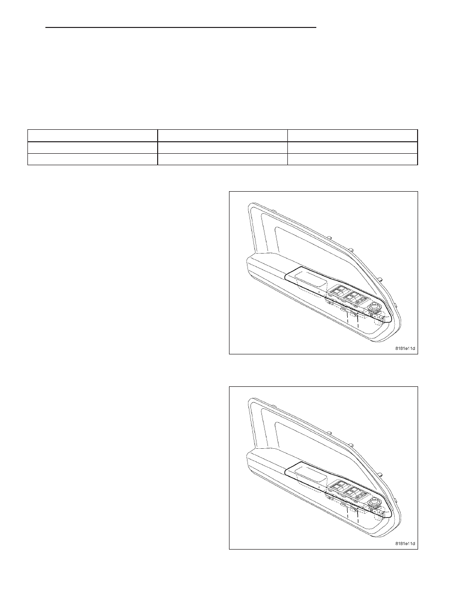
REMOVAL
1. Disconnect and isolate the battery negative cable.
2. Remove the front door bolster. (Refer to 23 -
BODY/DOOR - FRONT/DOOR - REMOVAL).
3. Disconnect the electrical harness connectors.
4. With the bolster on the bench, gently pry in on the
tabs of the mirror switch and push through the front
of the cover and remove.
INSTALLATION
1. Place the mirror switch in bolster opening and
firmly snap into place.
2. Connect the electrical harness connectors.
3. Install the front door bolster. (Refer to 23 - BODY/
DOOR - FRONT/DOOR - INSTALLATION)
4. Connect the battery negative cable.
PM
POWER LOCKS
8N - 49