Dodge Caliber. Manual - part 271
OPERATION
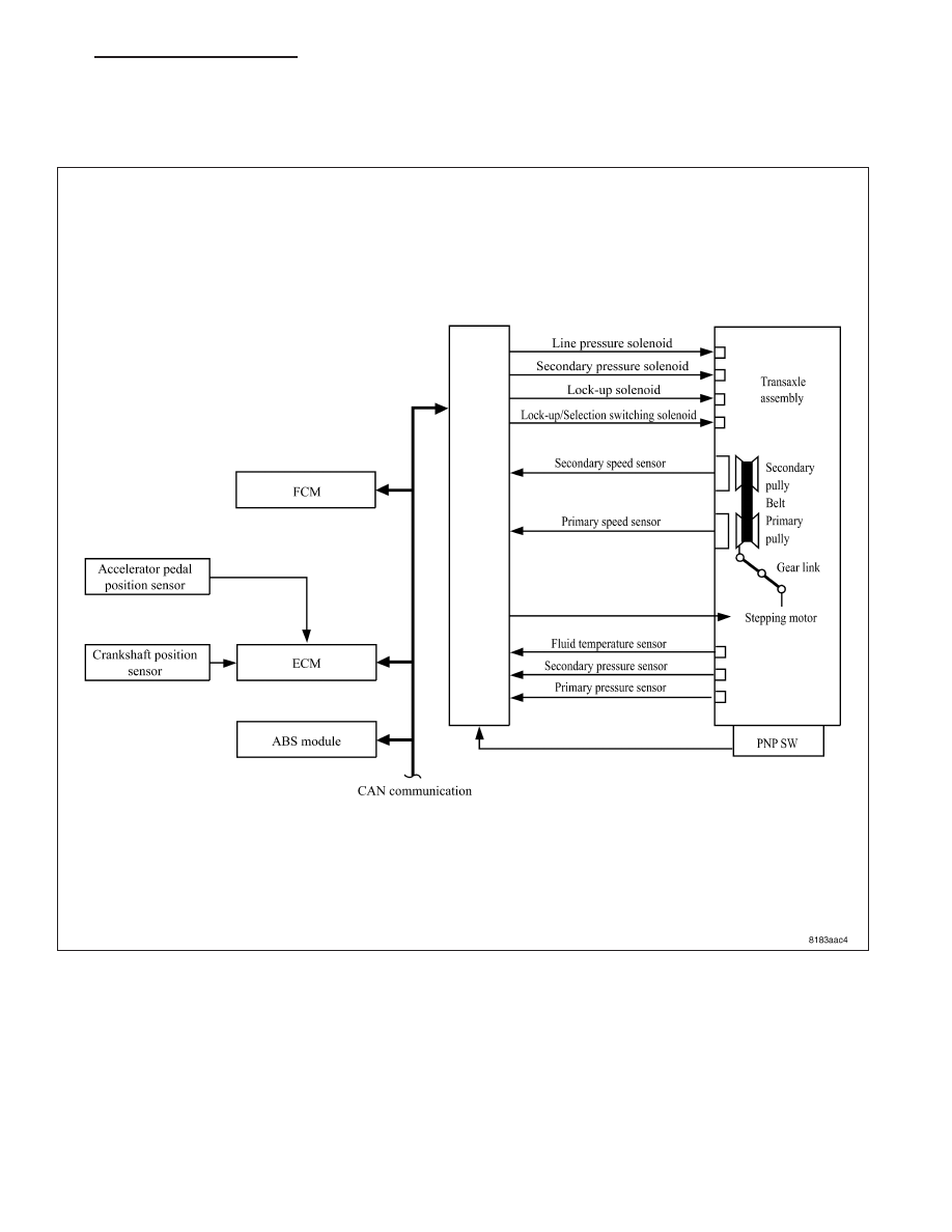
Shift Control
In order to select the gear ratio which can obtain the driving force in accordance with driver’s intention and the
vehicle condition, TCM monitors the driving conditions, such as the vehicle speed and the throttle position and
selects the optimum gear ratio, and determines the gear change steps to the gear ratio. Then it sends the command
to the stepping motor, and controls the flow-in/flow-out of line pressure to/from the primary pulley to determine the
position of the moving-pulley and control the gear ratio.
PM
ELECTRONIC CONTROL MODULES - SERVICE INFORMATION
8E - 195