Dodge Caliber. Manual - part 268


  Index      Dodge     Dodge Caliber - service repair manual 2007 year


Search            


Content   ..  266  267  268  269   ..


Dodge Caliber. Manual - part 268


DATA LINK CONNECTOR

DESCRIPTION

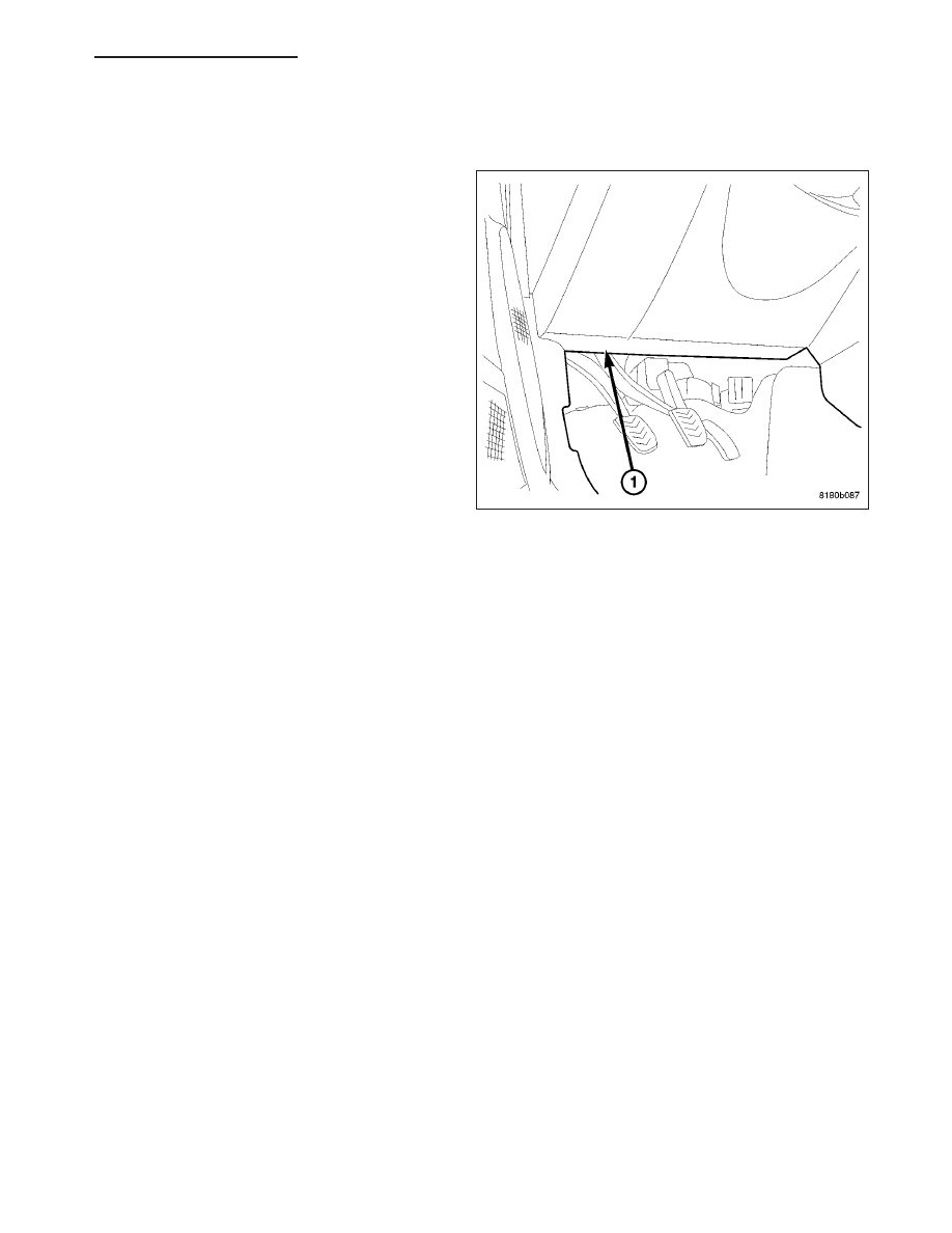
The Data Link Connector (DLC) (1) is a 16-way
molded plastic connector that is part of the instrument
panel wire harness. This connector is located at the
lower edge of the instrument panel, outboard of the
steering column. The connector insulator is retained
by integral snap features within a rectangular cutout in
a mounting bracket integral to the lower instrument
panel and inboard of the inside hood release on the
inner cowl side trim.

OPERATION

The Data Link Connector (DLC) is an industry-standard 16-way connector that permits the connection of a diag-
nostic scan tool to the Controller Area Network (CAN) data bus for interfacing with, configuring, and retrieving Diag-
nostic Trouble Code (DTC) data from the electronic modules that reside on the data bus network of the vehicle.

PM

ELECTRONIC CONTROL MODULES - SERVICE INFORMATION

8E - 183

HEATED SEAT MODULE

DESCRIPTION

The heated seat module (2) is located under the left
front seat. It has a single electrical connector (1) and
a push pin style retainer that secures it to the seat
pan. The module can be accessed from under the
front left seat with the seat in the full back position.

The heated seat module is a microprocessor designed
to use the Local Interface Network (LIN) data bus
messages from the instrument cluster also known as
the Cabin Compartment Node (CCN). The CCN
receives inputs from the heated seat switches and in
turn signals the heated seat module to operate the
heated seat elements for both front seats.

OPERATION

The heated seat module operates on fused battery current received from the ignition switch. The module is
grounded to the body at all times through the electrical connector. Inputs to the module include Local Interface
Network (LIN) data bus messages and standard hardwired 12 volt power and ground. In response to the LIN inputs
the heated seat module will control the battery current to the appropriate heated seat elements.

When a heated seat switch LIN data bus signal is received by the heated seat module, the module energizes the
selected heated seat element. The Low heat set point is about 38°C (100.4°F), and the High heat set point is about
42°C (107.6°F).

In addition to operating the heated seat elements, the heated seat module sends LED illumination messages to the
CNN via the LIN data bus. The CNN then sends the LED illumination message to the accessory switch bank so that
the appropriate LEDs are illuminated for any given heating level. Pressing the switch once will select high-level
heating. Pressing the switch a second time will select low-level heating. Pressing the switch a third time will shut the
heating elements off.

If the heated seat module detects a heated seat element OPEN or SHORT circuit, it will record and store the appro-
priate diagnostic trouble code (DTC).

DIAGNOSIS AND TESTING

HEATED SEAT MODULE

In order to obtain conclusive testing, the heated seat system and the Local Interface Network (LIN) data bus circuit
must be checked. Any diagnosis of the heated seat system should begin with, the use of a scan tool and the
appropriate diagnostic service information.

Refer to the appropriate wiring information for complete circuit schematic or connector pin-out information.

NOTE: Vehicles equipped with the heated seat option utilize a low voltage cut-off feature. This feature turns
off power to the heated seat system anytime vehicle voltage is below 11.7v or above 15.5v. Be certain to
check the vehicle electrical system for proper voltage anytime the power seat system appears inoperative.

Before any testing of the heated seat system is attempted, the battery should be fully-charged.

8E - 184

ELECTRONIC CONTROL MODULES - SERVICE INFORMATION

PM

REMOVAL

CAUTION: The Heated Seat Module mounting tab
can be damaged during module removal and
installation. Use care to properly align tab to pre-
vent binding that could result in tab breakage.

1. Position the right front seat to the full rearward

position.

2. Disconnect and isolate the battery negative cable.

3. Disconnect the wire harness connector (4) from the

heated seat module (3).

4. Unsnap the heated seat module retaining tab (2)

from the seat pan (1).

5. Remove the heated seat module (3) from the

vehicle.

INSTALLATION

CAUTION: The Heated Seat Module mounting tab can be damaged during module removal and installation.
Use care to properly align tab to prevent binding that could result in tab breakage.

1. Install the heated seat module (3) into the vehicle.

2. Position the retaining tab (2) with the mounting

hole in the seat pan (1). Firmly apply even pres-
sure to the module (3) until the mounting tab is
fully seated.

3. Connect the wire harness connector (4) to the

heated seat module (3).

4. Connect the battery negative cable.

5. Check for proper heated seat system operation.

PM

ELECTRONIC CONTROL MODULES - SERVICE INFORMATION

8E - 185

MODULE-POWERTRAIN CONTROL

DESCRIPTION

PCM GROUND

Ground is provided through multiple pins of the PCM connector. Depending on the vehicle there may be as many
as two different ground pins. There are power grounds and sensor grounds.

The power grounds are used to control the ground side relays, solenoids, ignition coil or injectors. The signal ground
is used for any input that uses sensor return for ground, and the ground side of any internal processing component.

The PCM case is shielded to prevent RFI and EMI. The PCM case is grounded and must be firmly attached to a
good, clean body ground.

Internally all grounds are connected together, however there is noise suppression on the sensor ground. For EMI
and RFI protection the housing and cover are also grounded separately from the ground pins.

SENSOR RETURN - PCM INPUT

The sensor return circuit provides a low electrical noise ground reference for all of the systems sensors. The sensor
return circuit connects to internal ground circuits within the Powertrain Control Module (PCM).

IGNITION SENSE - PCM INPUT

The ignition sense input informs the Powertrain Control Module (PCM) that the ignition switch is in the crank or run
position.

OPERATION

POWERTRAIN CONTROL MODULE

The PCM receives input signals from various switches
and sensors that are referred to as PCM Inputs.
Based on these inputs, the PCM adjusts various
engine and vehicle operations through devices that
are referred to as PCM Outputs.

NOTE: PCM Inputs:

Air Conditioning Controls

Battery Voltage

Brake Switch

Camshaft Position Sensor

Clutch Upstop Switch

Clutch Interlock

Crankshaft Position Sensor

8E - 186

ELECTRONIC CONTROL MODULES - SERVICE INFORMATION

PM


Content   ..  266  267  268  269   ..