Dodge Caliber. Manual - part 245


  Index      Dodge     Dodge Caliber - service repair manual 2007 year


Search            


Content   ..  243  244  245  246   ..


Dodge Caliber. Manual - part 245


8.

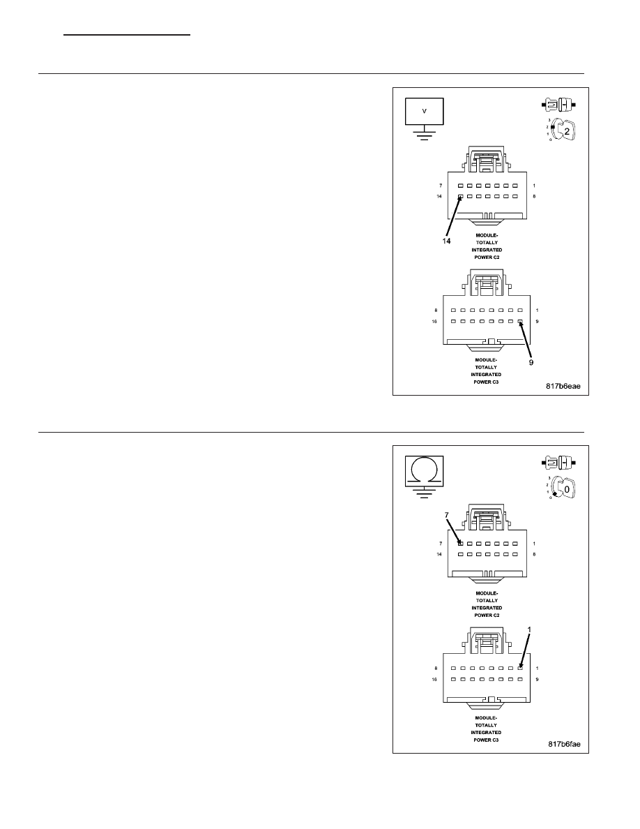
(D64) CAN C BUS (-) CIRCUIT SHORTED TO VOLTAGE

Measure the voltage between the (D64) CAN C Bus (-) circuit and
ground.

Is there any voltage present?

Yes

>> Repair the (D64) CAN C Bus (-) circuit for a short to volt-

age.

Perform BODY VERIFICATION TEST – VER 1. (Refer to 8
-

ELECTRICAL/ELECTRONIC

CONTROL MODULES

-

STANDARD PROCEDURE)

No

>> Go To 9

9.

(D65) CAN C BUS (+) CIRCUIT SHORTED TO GROUND

Turn the ignition off.

Measure the resistance between ground and the (D65) CAN C Bus (+)
circuit.

Is any resistance present?

Yes

>> Repair the (D65) CAN C Bus (+) circuit for a short to

ground.

Perform BODY VERIFICATION TEST – VER 1. (Refer to 8
-

ELECTRICAL/ELECTRONIC

CONTROL MODULES

-

STANDARD PROCEDURE)

No

>> Go To 10

PM

ELECTRONIC CONTROL MODULES - ELECTRICAL DIAGNOSTICS

8E - 91

10.

(D64) CAN C BUS (-) CIRCUIT SHORTED TO GROUND

Measure the resistance between ground and the (D64) CAN C Bus (-)
circuit.

Is any resistance present?

Yes

>> Repair the (D64) CAN C Bus (-) circuit for a short to

ground.

Perform BODY VERIFICATION TEST – VER 1. (Refer to 8
-

ELECTRICAL/ELECTRONIC

CONTROL MODULES

-

STANDARD PROCEDURE)

No

>> Go To 11

11.

(D65) CAN C BUS (+) CIRCUIT SHORTED TO (D64) CAN C BUS (-) CIRCUIT

Measure the resistance between the (D65) CAN C Bus (+) circuit and
the (D64) CAN C Bus (-) circuit.

Is any resistance present?

Yes

>> Repair the (D65) CAN C Bus (+) circuit for a short to the

(D64) CAN C Bus (-) circuit.

Perform BODY VERIFICATION TEST – VER 1. (Refer to 8
-

ELECTRICAL/ELECTRONIC

CONTROL MODULES

-

STANDARD PROCEDURE)

No

>> Inspect the wiring and connectors for damage or shorted

circuits. If ok, replace and program the TIPM in accordance
with the service information.

Perform BODY VERIFICATION TEST – VER 1. (Refer to 8
-

ELECTRICAL/ELECTRONIC

CONTROL MODULES

-

STANDARD PROCEDURE).

8E - 92

ELECTRONIC CONTROL MODULES - ELECTRICAL DIAGNOSTICS

PM

U1107-ECU IN SINGLE-WIRE MODE

For a complete wiring diagram Refer to Section 8W.

PM

ELECTRONIC CONTROL MODULES - ELECTRICAL DIAGNOSTICS

8E - 93

When Monitored:
With the ignition on.

Set Condition:
The TIPM detects an open, a short high, a short low or a short together in either of the CAN B Bus circuits.

Possible Causes

(D55) CAN B BUS (+) CIRCUIT SHORTED TO GROUND

(D54) CAN B BUS (-) CIRCUIT SHORTED TO GROUND

(D55) CAN B BUS (+) CIRCUIT SHORTED TO VOLTAGE

(D54) CAN B BUS (-) CIRCUIT SHORTED TO VOLTAGE

(D55) CAN B BUS (+) CIRCUIT SHORTED TO (D54) CAN B BUS (-) CIRCUIT

(D55) CAN B BUS (+) CIRCUIT OPEN

(D54) CAN B BUS (-) CIRCUIT OPEN

ANY CAN B BUS MODULE

Diagnostic Test

1.

TEST FOR INTERMITTENT CONDITION

Turn the ignition on.

With the scan tool, record and erase TIPM DTC’s.

Cycle the ignition from on to off 3 times.

Turn the ignition on.

With the scan tool, read active TIPM DTC’s.

Does the scan tool display this DTC as active?

Yes

>> Go To 2

No

>> The conditions that caused this code to set are not present at this time. Using the wiring diagram/sche-

matic as a guide, inspect the wiring and connectors.

2.

ANY CAN B BUS MODULE— INTERNAL FAULT

Turn the ignition off.

With the scan tool, monitor the active TIPM DTC’s.

While monitoring the scan tool, disconnect each CAN B Bus module one at a time.

NOTE: When performing the above step, turn the ignition off (wait one minute) before disconnecting any
module. When the module is disconnected turn the ignition on.

NOTE: This is to determine if the fault is internal within a module.
Check for this DTC to become active after disconnecting each CAN B Bus module the vehicle is equipped with.

NOTE: If the DTC becomes stored when a particular CAN B Bus module is disconnected, that module is
causing the DTC to set.

With all the CAN B Bus modules disconnected did the TIPM still set this DTC as active?

Yes

>> Go To 3

No

>> Replace the module that when disconnected the DTC became stored.

Perform BODY VERIFICATION TEST – VER 1. (Refer to 8 - ELECTRICAL/ELECTRONIC CONTROL
MODULES - STANDARD PROCEDURE).

8E - 94

ELECTRONIC CONTROL MODULES - ELECTRICAL DIAGNOSTICS

PM


Content   ..  243  244  245  246   ..