Content .. 1345 1346 1347 1348 ..
Dodge Caliber. Manual - part 1347
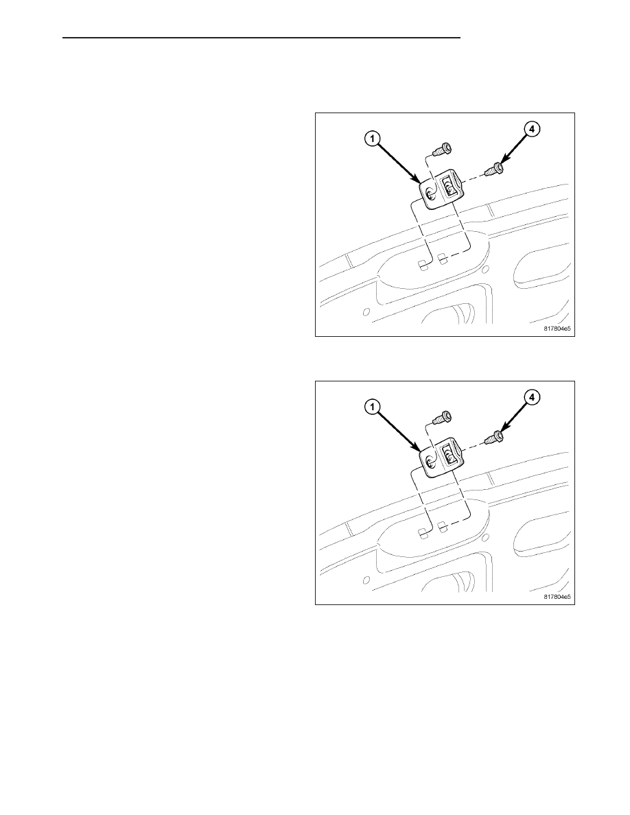
STRIKER
REMOVAL
1. Open the liftgate.
2. Remove the liftgate sill scuff plate (Refer to 23 -
BODY/INTERIOR/SCUFF PLATE-LIFTGATE SILL -
REMOVAL).
NOTE: Place a reference mark along the outer
edge of the striker to ensure it is reinstalled to its
original position.
3. Mark the position of the striker (1) on the liftgate
opening lower panel to aid installation.
4. Remove the two screws (4) that secure the striker
to the lower panel and remove the striker.
INSTALLATION
1. Position the liftgate striker (1) onto the liftgate
opening lower panel and align the striker to the
previously marked location.
2. Install the two bolts (4) that secure the striker to
the lower panel. Tighten the bolts to 23 N·m (17 ft.
lbs.).
3. Verify liftgate alignment and latch operation. The
liftgate should fit flush and have even gaps to adja-
cent body panels. Gap specifications are as fol-
lows:
•
7 mm (0.280 in.) to the fascia.
•
6 mm (0.240 in.) to the roof header.
•
4 mm (0.160 in.) to the body side.
4. Install the liftgate sill scuff plate (Refer to 23 -
BODY/INTERIOR/SCUFF PLATE-LIFTGATE SILL -
INSTALLATION).
PM
LIFTGATE
23 - 125