Dodge Caliber. Manual - part 1166


  Index      Dodge     Dodge Caliber - service repair manual 2007 year


Search            


Content   ..  1164  1165  1166  1167   ..


Dodge Caliber. Manual - part 1166


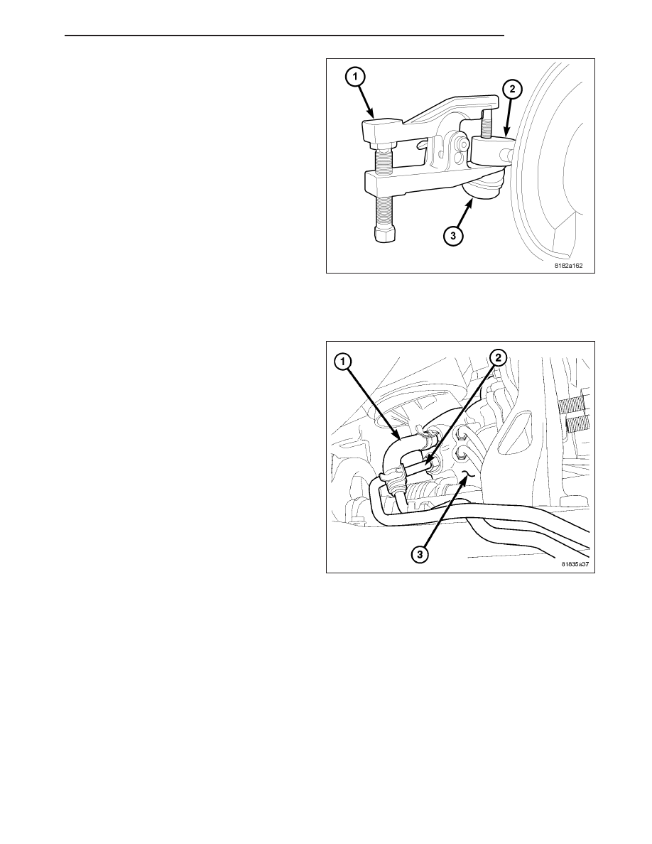
9. On each side of the gear, separate the tie rod end

(3) from the knuckle (2) using Remover (1), Special
Tool 9360.

10. If equipped, remove the engine belly pan. (Refer to 23 - BODY/EXTERIOR/BELLY PAN - REMOVAL)

11. Remove the rear engine mount. (Refer to 9 - ENGINE/ENGINE MOUNTING/REAR MOUNT - REMOVAL)

12. Remove the front engine mount through-bolt.

13. Remove the return hose (1) at the steering gear

(3).

14. Remove the pressure hose (2) at the steering

gear (3).

PM

GEAR

19 - 51

15. Remove the screws (1) securing the power steer-

ing hose routing clamps (2) to the crossmember.

16. Remove the screws (1) securing the stabilizer

bushing retainers (3) to the crossmember.

17. Remove the two stabilizer bushing retainers.

19 - 52

GEAR

PM

NOTE: Before removing the front suspension crossmember from the vehicle, the location of the crossmem-
ber must be marked on the body of the vehicle. Do this so the crossmember can be relocated, upon rein-
stallation, against the body of vehicle in the same location as before removal. If the front suspension
crossmember is not reinstalled in exactly the same location as before removal, the preset front wheel align-
ment settings (caster and camber) may be lost.

18. Mark the location of the front crossmember on the body near each mounting bolt using a marker or crayon. Do

not use a scratch awl or other tool that can penetrate the protective coating on the body.

19. Support the front crossmember with a transmission jack.

20. Remove the four mounting bolts (6) securing the front crossmember (1) to the body.

21. Lower the crossmember enough to access the

intermediate shaft coupling (1) at the steering
gear pinion shaft (4). Slide the coupling off the
pinion shaft.

22. Remove the dash seals (3, 5) as necessary.

PM

GEAR

19 - 53

23. Remove the two bolts (1) securing the steering

gear (2) to the crossmember.

24. Rotate the stabilizer bar up in order to remove the

steering gear from the vehicle.

25. Remove the steering gear from the crossmember.

INSTALLATION

1. Rotate the stabilizer bar up and install the steering

gear on the crossmember.

2. Install the two bolts (1) securing the steering gear

(2) to the crossmember. Tighten the steering gear
mounting bolts to 70 N·m (52 ft. lbs.).

19 - 54

GEAR

PM


Content   ..  1164  1165  1166  1167   ..