Dodge Caliber. Manual - part 110


  Index      Dodge     Dodge Caliber - service repair manual 2007 year


Search            


Content   ..  108  109  110  111   ..


Dodge Caliber. Manual - part 110


3.

BRAKE FLUID LEVEL SWITCH INTERNAL FAILURE

Turn the ignition off.

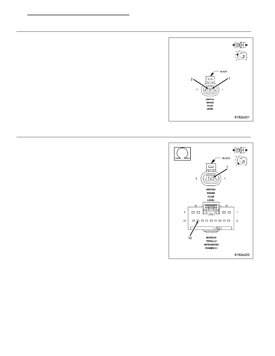
Connect a jumper wire between the (B20) Brake Fluid Level signal cir-
cuit and the (Z925) Brake Fluid Level ground circuit in the Brake Fluid
Level Switch harness connector

Turn the ignition on.

With the scan tool, read the Brake Fluid Level Switch voltage

Is the voltage below 1.0 volt?

Yes

>> Replace the Brake Fluid Level Switch in accordance with

the Service Information.

Perform ABS VERIFICATION TEST. (Refer to 5 - BRAKES -
STANDARD PROCEDURE).

No

>> Go To 4

4.

(B20) BRAKE FLUID LEVEL SWITCH CIRCUIT OPEN

Turn the ignition off.

Disconnect the Brake Fluid Level Switch.

Disconnect the TIPM harness connector.

Measure the resistance of the (B20) Brake Fluid Level signal circuit
between the Brake Fluid Level Switch harness connector and the TIPM
harness connector.

Is the resistance below 5 ohms?

Yes

>> Go To 5

No

>> Repair the open in the (B20) Brake Fluid Level Switch sig-

nal circuit.

Perform ABS VERIFICATION TEST. (Refer to 5 - BRAKES -
STANDARD PROCEDURE).

PM

BRAKES - ABS ELECTRICAL DIAGNOSTICS

5 - 141

5.

(Z925) SENSOR GROUND CIRCUIT OPEN

Turn the ignition off.

Disconnect the Brake Fluid Level Switch harness connector.

Reconnect the TIPM harness connector.

Measure the resistance of the (Z925) Brake Fluid Level Switch ground
circuit between the Brake Fluid Level Switch harness connector and
ground.

Is the resistance below 5.0 ohms?

Yes

>> Replace and program the Totally Integrated Power Module

in accordance with the Service Information.

Perform ABS VERIFICATION TEST. (Refer to 5 - BRAKES -
STANDARD PROCEDURE).

No

>> Repair the open in the (Z925) Sensor ground circuit.

Perform ABS VERIFICATION TEST. (Refer to 5 - BRAKES -
STANDARD PROCEDURE).

5 - 142

BRAKES - ABS ELECTRICAL DIAGNOSTICS

PM

C100A–LEFT FRONT WHEEL SPEED SENSOR CIRCUIT

For a complete wiring diagram Refer to Section 8W.

PM

BRAKES - ABS ELECTRICAL DIAGNOSTICS

5 - 143

When Monitored:
With the ignition on.

Set Condition:
When the Left Front Wheel Speed Sensor circuit fails the diagnostic test.

Possible Causes

CONNECTOR/TERMINAL DAMAGE

(B9) LEFT FRONT WSS SUPPLY CIRCUIT SHORTED TO VOLTAGE, GROUND OR OPEN

(B8) LEFT FRONT WSS SIGNAL CIRCUIT SHORTED TO VOLTAGE, GROUND, OR OPEN

(B8) LEFT FRONT WSS SIGNAL CIRCUIT AND (B9) LEFT FRONT WSS SUPPLY CIRCUIT SHORTED
TOGETHER

LEFT FRONT WSS

ANTI-LOCK BRAKE MODULE

Diagnostic Test

1.

CHECK FOR DTC C100A–LEFT FRONT WHEEL SPEED SENSOR CIRCUIT

NOTE: This DTC must be active for the results of this test to be valid.
Turn the ignition on.

With the scan tool, record and erase DTCs.

Cycle the ignition switch from off to on.

With the scan tool, read DTCs.

NOTE: The Anti-Lock Brake Module must sense ALL 4 wheels at 12 km/h (7.5 mph) before it will extinguish
the ABS indicators.

Does the scan tool display: C100A–LEFT FRONT WHEEL SPEED SENSOR CIRCUIT?

Yes

>> Go To 2

No

>> The condition that caused the symptom is currently not present. Inspect the related wiring for a possible

intermittent condition. Look for any chafed, pierced, pinched, or partially broken wires.

Refer to the ABS-INTERMITTENT CONDITION TEST. (Refer to 5 - BRAKES - DIAGNOSIS AND TEST-
ING)

2.

CHECK CONNECTOR/TERMINAL FOR DAMAGE

NOTE: Check all terminals for broken, bent, pushed out, or corroded terminals.
Turn the ignition off.

Inspect the Anti-Lock Brake Module harness connector, Left Front WSS, and Left Front WSS harness connector.

Is the Left Front WSS or any of the connectors/terminals damaged?

Yes

>> Repair as necessary.

Perform ABS VERIFICATION TEST. (Refer to 5 - BRAKES - STANDARD PROCEDURE).

No

>> Go To 3

5 - 144

BRAKES - ABS ELECTRICAL DIAGNOSTICS

PM


Content   ..  108  109  110  111   ..