Dodge Caliber. Manual - part 57


  Index      Dodge     Dodge Caliber - service repair manual 2007 year


Search            


Content   ..  55  56  57  58   ..


Dodge Caliber. Manual - part 57


5.

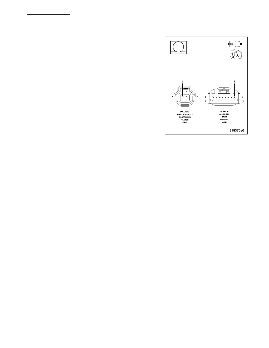
(T312) REAR DIFFERENTIAL SOLENOID CONTROL CIRCUIT OPEN

Measure the resistance of the (T312) Rear Differential Solenoid Control
circuit between the ECC Solenoid harness connector and the AWD
Control Module harness connector.

Is the resistance below 5.0 ohms?

Yes

>> Go To 6

No

>> Repair the open in the (T312) Rear Differential Solenoid

Control circuit.

Perform AWD Control Module VERIFICATION TEST. (Refer
to 3 - DIFFERENTIAL & DRIVELINE/ELECTRONICALLY
CONTROLLED CLUTCH - STANDARD PROCEDURE)

6.

AWD CONTROL MODULE

NOTE: Before continuing, check the AWD Control Module harness connector terminals for corrosion, dam-
age, or terminal push out. Repair as necessary.
Using the schematics as a guide, inspect the wire harness and connectors. Pay particular attention to all Power and
Ground circuits.

Were there any problems found?

Yes

>> Repair as necessary.

Perform AWD Control Module VERIFICATION TEST. (Refer to 3 - DIFFERENTIAL & DRIVELINE/ELEC-
TRONICALLY CONTROLLED CLUTCH - STANDARD PROCEDURE)

No

>> Replace AWD Control Module in accordance with Service Information.

Perform AWD Control Module VERIFICATION TEST. (Refer to 3 - DIFFERENTIAL & DRIVELINE/ELEC-
TRONICALLY CONTROLLED CLUTCH - STANDARD PROCEDURE)

7.

ELECTRONICALLY CONTROLLED CLUTCH (ECC)

NOTE: Before continuing, check the ECC Solenoid jumper harness connector terminals for corrosion, dam-
age, or terminals push out, repair/replace as necessary.
Using the schematics as a guide, inspect the wire harness and connectors. Pay particular attention to all Power and
Ground circuits.

Were there any problems found?

Yes

>> Repair as necessary.

Perform AWD Control Module VERIFICATION TEST. (Refer to 3 - DIFFERENTIAL & DRIVELINE/ELEC-
TRONICALLY CONTROLLED CLUTCH - STANDARD PROCEDURE)

No

>> Replace ECC in accordance with Service Information.

Perform AWD Control Module VERIFICATION TEST. (Refer to 3 - DIFFERENTIAL & DRIVELINE/ELEC-
TRONICALLY CONTROLLED CLUTCH - STANDARD PROCEDURE)

PM

CLUTCH-ELECTRONICALLY CONTROLLED-ELECTRICAL DIAGNOSTICS

3 - 103

8.

INTERMITTENT WIRING AND CONNECTORS

The conditions necessary to set this DTC are not present at this time.

Using the schematics as a guide, inspect the wiring and connectors specific to this circuit.

Wiggle test the wiring harness and connectors while checking for shorted and open circuits.

Using the scan tool, monitor the data related to this circuit while performing the wiggle test. Look for the data to
change or for the DTC to reset.

Were there any problems found?

Yes

>> Repair as necessary.

Perform AWD Control Module VERIFICATION TEST. (Refer to 3 - DIFFERENTIAL & DRIVELINE/ELEC-
TRONICALLY CONTROLLED CLUTCH - STANDARD PROCEDURE)

No

>> Test Complete.

3 - 104

CLUTCH-ELECTRONICALLY CONTROLLED-ELECTRICAL DIAGNOSTICS

PM

C145F–AWD SYSTEM TEMPORARILY DISABLED — OVERTEMPERATURE

For a complete wiring diagram Refer to Section 8W.

When Monitored:
Ignition on.

Set Condition:
The AWD Control Module detects overload condition due to excessive torque being applied to the ECC from
hard driving conditions (Mud, Sand, Snow etc.).

Possible Causes

DRIVING CONDITIONS

ALL WHEEL DRIVE (AWD) CONTROL MODULE

ELECTRONICALLY CONTROLLED CLUTCH (ECC)

Always perform the AWD Pre-Diagnostic Troubleshooting procedure before proceeding. (Refer to 3 -
DIFFERENTIAL & DRIVELINE/ELECTRONICALLY CONTROLLED CLUTCH - STANDARD PROCEDURE).

Diagnostic Test

1.

DTC IS ACTIVE

NOTE: If C1456, C145A or C145D has set along with this DTC, diagnose those DTC(s) first before continu-
ing.
Ignition on, engine not running.

With the scan tool, select View DTCs.

Is the status Active for this DTC?

Yes

>> Go To 2

Perform AWD Control Module VERIFICATION TEST. (Refer to 3 - DIFFERENTIAL & DRIVELINE/ELEC-
TRONICALLY CONTROLLED CLUTCH - STANDARD PROCEDURE)

No

>> Go To 4

2.

VERIFY SET CONDITION

Check with customer on driving terrain (e.g. mud, sand, snow) for set condition.

With the scan tool, erase DTC’s.

Test drive vehicle on dry paved road.

With the scan tool, read DTC’s.

Is the status Active for this DTC?

Yes

>> Go To 3

No

>> Test Complete.

Perform AWD Control Module VERIFICATION TEST. (Refer to 3 - DIFFERENTIAL & DRIVELINE/ELEC-
TRONICALLY CONTROLLED CLUTCH - STANDARD PROCEDURE)

PM

CLUTCH-ELECTRONICALLY CONTROLLED-ELECTRICAL DIAGNOSTICS

3 - 105

3.

AWD CONTROL MODULE

NOTE: Before continuing, check the AWD Control Module harness connector terminals for corrosion, dam-
age, or terminal push out. Repair as necessary.
Using the schematics as a guide, inspect the wire harness and connectors. Pay particular attention to all Power and
Ground circuits.

Were there any problems found?

Yes

>> Repair as necessary.

Perform AWD Control Module VERIFICATION TEST. (Refer to 3 - DIFFERENTIAL & DRIVELINE/ELEC-
TRONICALLY CONTROLLED CLUTCH - STANDARD PROCEDURE)

No

>> Replace AWD Control Module in accordance with Service Information.

Perform AWD Control Module VERIFICATION TEST. (Refer to 3 - DIFFERENTIAL & DRIVELINE/ELEC-
TRONICALLY CONTROLLED CLUTCH - STANDARD PROCEDURE)

4.

INTERMITTENT WIRING AND CONNECTORS

The conditions necessary to set this DTC are not present at this time.

Using the schematics as a guide, inspect the wiring and connectors specific to this circuit.

Wiggle test the wiring harness and connectors while checking for shorted and open circuits.

Using the scan tool, monitor the data related to this circuit while performing the wiggle test. Look for the data to
change or for the DTC to reset.

Were there any problems found?

Yes

>> Repair as necessary.

Perform AWD Control Module VERIFICATION TEST. (Refer to 3 - DIFFERENTIAL & DRIVELINE/ELEC-
TRONICALLY CONTROLLED CLUTCH - STANDARD PROCEDURE)

No

>> Test Complete.

3 - 106

CLUTCH-ELECTRONICALLY CONTROLLED-ELECTRICAL DIAGNOSTICS

PM


Content   ..  55  56  57  58   ..