Dodge Caliber. Manual - part 14


  Index      Dodge     Dodge Caliber - service repair manual 2007 year


Search            


Content   ..  12  13  14  15   ..


Dodge Caliber. Manual - part 14


INSTALLATION

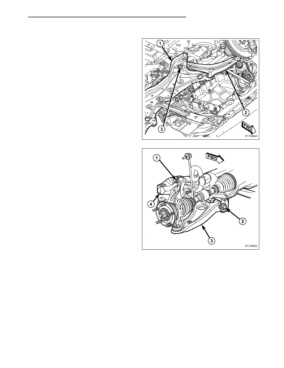
1. Place the lower control arm (2) into the front sus-

pension crossmember (1).

2. Insert the rear bolt (3) up through the crossmember

(1) and lower control arm (2).

3. Install, but do not fully tighten, the nut (1) on the

rear bolt attaching the lower control arm (3) to the
crossmember (4).

4. Install, but do not fully tighten, the front bolt (2)

attaching the lower control arm to the crossmem-
ber.

5. With no weight or obstruction on the lower control

arm, tighten the lower control arm rear mounting
bolt nut (1) to 183 N·m (135 ft. lbs.).

6. With no weight or obstruction on the lower control

arm, tighten the lower control arm front pivot bolt
(2) to 183 N·m (135 ft. lbs.).

PM

FRONT SUSPENSION

2 - 21

7. Install the ball joint (6) stud into the knuckle (3),

aligning the bolt hole in the knuckle boss with the
groove formed in the side of the ball joint stud.

8. Install a NEW ball joint stud pinch bolt (4) and nut

(5). Tighten the nut to 82 N·m (60 ft. lbs.).

9. Install tire and wheel assembly (1) (Refer to 22 -

TIRES/WHEELS - INSTALLATION). Install and
tighten wheel mounting nuts (3) to 135 N·m (100 ft.
lbs.).

10. Lower the vehicle.

11. Perform wheel alignment as necessary. (Refer to

2 - SUSPENSION/WHEEL ALIGNMENT - STAN-
DARD PROCEDURE)

2 - 22

FRONT SUSPENSION

PM

BAR-STABILIZER

REMOVAL

NOTE: Before proceeding, (Refer to 2 - SUSPENSION/FRONT - WARNING).

1. Raise and support the vehicle. (Refer to LUBRICATION & MAINTENANCE/HOISTING - STANDARD PROCE-

DURE)

2. If equipped, remove the engine belly pan. (Refer to 23 - BODY/EXTERIOR/BELLY PAN - REMOVAL)

3. Remove the rear engine mount. (Refer to 9 - ENGINE/ENGINE MOUNTING/REAR MOUNT - REMOVAL)

4. Remove the front engine mount through-bolt.

5. Remove the bolts (1) securing the power steering

hose routing clamps (2) to the crossmember.

6. At each end of the stabilizer bar, while holding the

stabilizer bar link (1) lower stud stationary, remove
the nut (3) securing the link to the stabilizer bar (2).

PM

FRONT SUSPENSION

2 - 23

7. Remove the screws (1) securing the stabilizer

bushing retainers (3) to the crossmember.

8. Remove the two stabilizer bushing retainers.

9. Utilizing the slit cut into the cushions (bushings),

remove the two cushions from the stabilizer bar.

NOTE: Before removing the front suspension crossmember from the vehicle, the location of the crossmem-
ber must be marked on the body of the vehicle. Do this so the crossmember can be relocated, upon rein-
stallation, against the body of vehicle in the same location as before removal. If the front suspension
crossmember is not reinstalled in exactly the same location as before removal, the preset front wheel align-
ment settings (caster and camber) may be lost.

10. Mark the location of the front crossmember on the body near each mounting bolt.

11. Support the crossmember with a transmission jack.

12. Remove the four mounting bolts (6) securing the front crossmember (1) to the body.

2 - 24

FRONT SUSPENSION

PM


Content   ..  12  13  14  15   ..