Dodge Nitro. Manual - part 930


  Index      Dodge     Dodge Nitro - service repair manual 2007 year


Search            


Content   ..  928  929  930  931   ..


Dodge Nitro. Manual - part 930


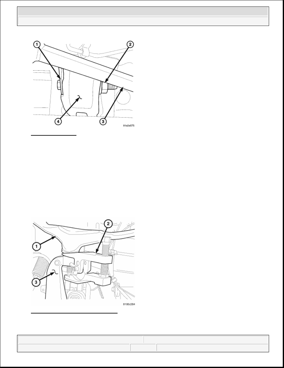
Fig. 73: Pivot Bolts 
Courtesy of CHRYSLER LLC 

9. Remove the upper control arm rear nut (2) by using a ratchet and extension under the steering shaft (3).  

10. Remove the upper control arm front bolt.  

11. Remove the upper control arm from the vehicle.  

UPPER CONTROL ARM - RIGHT 

1. Raise and support the vehicle.  

2. Remove the right side tire and wheel assembly.  

3. Remove the upper ball joint nut. 

Fig. 74: Upper Ball Joint Separation 
Courtesy of CHRYSLER LLC 

4. Separate the upper ball joint from the steering knuckle (3) using remover 9360 (2).  


2007 Dodge Nitro R/T 

2007 SUSPENSION Suspension - Nitro


5. Lower the vehicle.  

6. Remove the air box assembly. Refer to REMOVAL for 3.7L - SERVICE INFORMATION or 

REMOVAL for 4.0L - SERVICE INFOMATION.  

7. Remove the upper control arm rear bolt/nut.  

8. Remove the upper control arm front bolt/nut.  

9. Remove the upper control arm from the vehicle.  

INSTALLATION 

UPPER CONTROL ARM - LEFT 

Fig. 75: Pivot Bolts 
Courtesy of CHRYSLER LLC 

1. Install the upper control arm to the vehicle.  

2. Install the upper control arm front flag bolt (1). Tighten the nut (2) to 122 N.m (90 ft.lbs.) with full 

vehicle weight.  

3. Install the upper control arm rear flag bolt. Tighten the nut to 122 N.m (90 ft.lbs.) with full vehicle 

weight. 


2007 Dodge Nitro R/T 

2007 SUSPENSION Suspension - Nitro


Fig. 76: Identifying Battery Tray, Power Center & Battery 
Courtesy of CHRYSLER LLC 

4. Install the battery tray (1). Refer to INSTALLATION .  

5. Install the battery. Refer to INSTALLATION .  

6. Reclip and mount the power center (2).  

7. Install the upper ball joint nut. Tighten the nut to 41 N.m (30 ft.lbs.) plus an additional 90° turn.  

8. Install the left side tire and wheel assembly. Refer to STANDARD PROCEDURE .  

9. Lower the vehicle.  

10. Set the toe. See STANDARD PROCEDURE.  

UPPER CONTROL ARM - RIGHT 

1. Install the upper control arm to the vehicle.  

2. Install the upper control arm front flag bolt. Tighten the nut to 122 N.m (90 ft.lbs.) with full vehicle 

weight.  

3. Install the upper control arm rear flag bolt. Tighten the nut to 122 N.m (90 ft.lbs.) with full vehicle 

weight.  

4. Install the air box. Refer to INSTALLATION for 3.7L - SERVICE INFORMATION or 

INSTALLATION for 4.0L - SERVICE INFORMATION.  

5. Install the upper ball joint nut. Tighten the nut to 41 N.m (30 ft.lbs.) plus an additional 90° turn.  

6. Install the right side tire and wheel assembly. Refer to STANDARD PROCEDURE .  

7. Lower the vehicle.  

8. Set the toe. See STANDARD PROCEDURE.  

REAR 

DESCRIPTION 


2007 Dodge Nitro R/T 

2007 SUSPENSION Suspension - Nitro


REAR SUSPENSION 

Fig. 77: Rear Suspension Components 
Courtesy of CHRYSLER LLC 

The rear suspension is comprised of : 

Drive axle  

Shock absorbers (1)  

Coil springs (2)  

Lower suspension arms (5)  

Upper suspension arm  

Stabilizer bar (4)  

Stabilizer link (3)  

Track bar (6)  

WARNING 

REAR SUSPENSION 

NOTE:

Suspension components with rubber/urethane bushings should be tightened 
with the full weight of the vehicle at normal ride height. It is important to have 
the springs supporting the full weight of the vehicle when the fasteners are 
torqued. If springs are not at their normal ride position, vehicle ride comfort 
could be affected and premature bushing wear may occur.

WARNING:

Suspension components with rubber bushings must be tightened with the 
vehicle at normal ride height. It is important to have the springs 
supporting the weight of the vehicle when the fasteners are torqued. If 
springs are not at their normal ride position, vehicle ride comfort will be 


2007 Dodge Nitro R/T 

2007 SUSPENSION Suspension - Nitro


Content   ..  928  929  930  931   ..