Dodge Nitro. Manual - part 925


  Index      Dodge     Dodge Nitro - service repair manual 2007 year


Search            


Content   ..  923  924  925  926   ..


Dodge Nitro. Manual - part 925


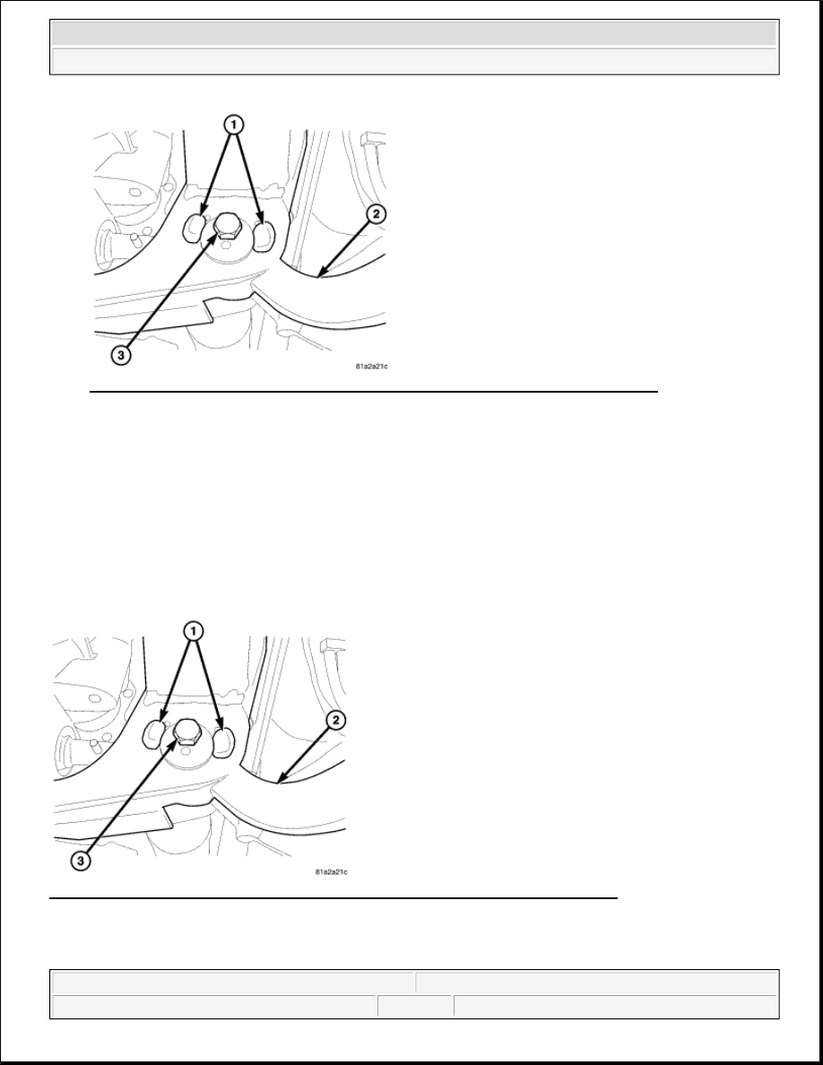
Fig. 40: Identifying Lower Control Arm, Control Arm Pivot Bolts & Rail Brackets 
Courtesy of CHRYSLER LLC 

6. Remove the control arm pivot bolts (3) and suspension arm from frame rail brackets (1).  

7. Remove the lower control arm (2) from the vehicle.  

INSTALLATION 

LOWER CONTROL ARM 

Fig. 41: Identifying Lower Control Arm, Control Arm Pivot Bolts & Rail Brackets 
Courtesy of CHRYSLER LLC 

1. Position the lower control arm (2) at the frame rail brackets. Install the cam/pivot bolts (3) and nuts. 

Tighten the nuts finger-tight. 

NOTE:

Marking the lower control arm pivot bolts front and rear will aid in the 
assembly procedure.


2007 Dodge Nitro R/T 

2007 SUSPENSION Suspension - Nitro


2. Install the ball joint into the steering knuckle and tighten the nut to 54 N.m (40 ft.lbs.) plus an additional 

90° turn. 

Fig. 42: Clevis Bracket 
Courtesy of CHRYSLER LLC 

3. Install shock absorber lower clevis bolt/nut (4). Tighten the nut to 150 N.m (110 ft.lbs.) with full vehicle 

weight. 

Fig. 43: Stabilizer Bar 
Courtesy of CHRYSLER LLC 

CAUTION: The ball joint stud taper must be CLEAN and DRY before installing 

into the knuckle. Clean the stud taper with mineral spirits to remove 
dirt and grease.


2007 Dodge Nitro R/T 

2007 SUSPENSION Suspension - Nitro


4. Install the stabilizer bar link lower bolt (2). Tighten the bolt to 102 N.m (75 ft.lbs.) with full vehicle 

weight . See INSTALLATION

Fig. 44: Identifying Lower Control Arm, Control Arm Pivot Bolts & Rail Brackets 
Courtesy of CHRYSLER LLC 

5. Align the marks front and rear (1) at the cam/pivot bolts (3) and tighten the nuts. Tighten the nuts to 170 

N.m (125 ft.lbs.) with full vehicle weight.  

6. Install the wheel and tire assembly, refer to STANDARD PROCEDURE .  

7. Remove the support and lower the vehicle.  

8. Perform a wheel alignment. See STANDARD PROCEDURE.  

SHOCK 

REMOVAL 

SHOCK - LEFT SIDE 


2007 Dodge Nitro R/T 

2007 SUSPENSION Suspension - Nitro


Fig. 45: Identifying Battery Tray, Power Center & Battery 
Courtesy of CHRYSLER LLC 

1. Disconnect the battery (3).  

2. Remove the battery. Refer to REMOVAL .  

3. Unclip the power center (2) and move it to the side out of the way to access the battery tray (1).  

4. Remove the battery tray (1). Refer to REMOVAL .  

5. Remove the four upper shock mounting nuts.  

6. Raise and support the vehicle.  

7. Remove the left tire and wheel assembly.  

8. Remove the caliper and support. Refer to REMOVAL . 

Fig. 46: Clevis Bracket 
Courtesy of CHRYSLER LLC 

9. Remove the lower bolt (4) at the lower control arm securing the clevis bracket (3). 


2007 Dodge Nitro R/T 

2007 SUSPENSION Suspension - Nitro


Content   ..  923  924  925  926   ..