Dodge Nitro. Manual - part 792


  Index      Dodge     Dodge Nitro - service repair manual 2007 year


Search            


Content   ..  790  791  792  793   ..


Dodge Nitro. Manual - part 792


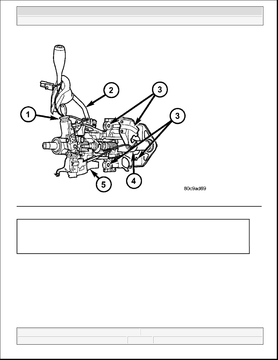
Fig. 18: Identifying Key Cylinder, Gear Shift Lever, Mounting Holes, Steering Column & Ignition Switch
Courtesy of CHRYSLER LLC
 

The ignition switch (5) is located on the steering column (4). It is used as the main on/off switching device for 
most electrical components. The mechanical key cylinder is used to engage/disengage the electrical ignition 
switch. 

OPERATION 

IGNITION SWITCH 

Vehicles equipped with an automatic transmission and a steering column mounted shifter: an interlock 
device is located within the shift cable. This interlock device is used to lock the transmission shifter in the 
PARK position when the key cylinder is in any position and the brake pedal is not depressed. 

1 - KEY CYLINDER
2 - GEAR SHIFT LEVER
3 - MOUNTING HOLES
4 - STEERING COLUMN
5 - IGNITION SWITCH


2007 Dodge Nitro R/T 

2007 ENGINE Ignition Control - Service Information - Nitro


DIAGNOSIS AND TESTING 

IGNITION SWITCH 

TEST AND REPAIR 

If the key removal effort is excessive on a vehicle with an automatic transmission first adjust the shift linkage, 
refer to ADJUSTMENTS . 

If the ignition switch effort is excessive, remove the ignition key cylinder from the steering column. Check the 
turning effort of the key cylinder. If the ignition key cylinder effort is excessive, replace the key cylinder. Refer 
to REMOVAL . 

REMOVAL 

IGNITION SWITCH 

SERVICE PRECAUTIONS 

Fig. 19: Identifying Key Cylinder, Gear Shift Lever, Mounting Holes, Steering Column & Ignition Switch
Courtesy of CHRYSLER LLC


2007 Dodge Nitro R/T 

2007 ENGINE Ignition Control - Service Information - Nitro


The tilt and standard column (4) have been designed to be serviced as an assembly; without wiring, switches, 
shrouds, steering wheel, etc. Most steering column components can be serviced without removing the steering 
column from the vehicle. See Fig. 19

Safety goggles should be worn at all times when working on steering columns. 

To service the steering wheel, switches or airbag, Refer to Electrical Restraints and follow all WARNINGS and 
CAUTIONS. 

The ignition key must be in the key cylinder for cylinder removal. The key cylinder must be removed first 
before removing ignition switch. 

1. Remove the negative (ground) cable from the battery.  

2. Disable the airbag, refer to REMOVAL .  

3. Remove the lower and upper shrouds.  

4. Remove key cylinder. Refer to REMOVAL 

1 - KEY CYLINDER
2 - GEAR SHIFT LEVER
3 - MOUNTING HOLES
4 - STEERING COLUMN
5 - IGNITION SWITCH

NOTE:

The steering column on vehicles equipped with an automatic transmission is 
not equipped with an internal locking shaft with the ignition cylinder. Alternative 
methods of locking the steering wheel for service will have to be used.

WARNING:

The airbag system is a sensitive, complex electro-mechanical unit. Before 
attempting to diagnose, remove or install the airbag system components 
you must first disconnect and isolate the battery negative (ground) cable. 
Then wait two minutes for the system capacitor to discharge. Failure to 
do so could result in accidental deployment of the air bag and possible 
personal injury. The fasteners, screws and bolts, originally used for the 
airbag components, have special coatings and are specifically designed 
for the airbag system. They must never be replaced with any substitutes. 
Anytime a new fastener is needed, replace with the correct fasteners 
provided in the service package or fasteners listed in the parts books.

CAUTION: Do not hammer on steering column shaft. This may cause damage to the 

shaft or bearing.

CAUTION: Do not attempt to remove the pivot bolts to disassemble the tilting 

mechanism.


2007 Dodge Nitro R/T 

2007 ENGINE Ignition Control - Service Information - Nitro


5. Disconnect the lower clockspring connectors.  

6. Remove the wire retainer from the tilt lever bracket. 

Fig. 20: Ignition Switch & Tilt Lever Mechanism 
Courtesy of CHRYSLER LLC 

7. Remove the tilt lever mounting screws to gain access to the ignition switch (1) mounting screws. See Fig. 

20 

1 - IGNITION SWITCH
2 - TILT LEVER MECHANISM


2007 Dodge Nitro R/T 

2007 ENGINE Ignition Control - Service Information - Nitro


Content   ..  790  791  792  793   ..