Dodge Nitro. Manual - part 778


  Index      Dodge     Dodge Nitro - service repair manual 2007 year


Search            


Content   ..  776  777  778  779   ..


Dodge Nitro. Manual - part 778


RECEIVER/DRIER-A/C 

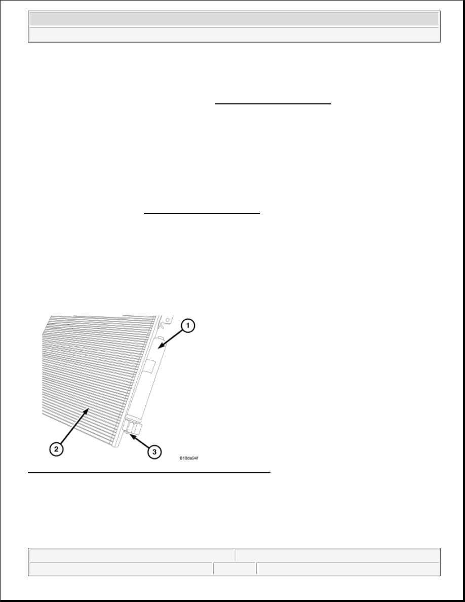
Fig. 200: A/C Receiver/Drier, Left Side A/C Condenser & Bolt 
Courtesy of CHRYSLER LLC 

1. Remove the tape or plugs from the receiver/drier fittings and the condenser ports.  

2. Lubricate new O-ring seals with clean refrigerant oil and install them onto the receiver/drier fittings. Use 

CAUTION: Be certain to adjust the refrigerant oil level when servicing the A/C 

refrigerant system. See REFRIGERANT OIL LEVEL. Failure to properly 
adjust the refrigerant oil level will prevent the A/C system from operating 
as designed and can cause serious A/C compressor damage.

CAUTION: The receiver/drier must be replaced if an internal failure of the A/C 

compressor has occurred. Failure to replace the receiver/drier can cause 
serious A/C compressor damage.

NOTE:

When replacing multiple A/C system components, refer to the Refrigerant Oil 
Capacities chart to determine how much oil should be added to the refrigerant 
system. See REFRIGERANT OIL LEVEL.

NOTE:

If only the receiver/drier is being replaced, add 30 milliliters (1 fluid ounce) of 
refrigerant oil to the refrigerant system. Use only the refrigerant oil of the type 
recommended for the A/C compressor in the vehicle.

NOTE:

Replacement of the refrigerant line O-ring seals and gaskets is required anytime 
a refrigerant line is opened. Failure to replace the rubber O-ring seals and metal 
gaskets could result in a refrigerant system leak.

NOTE:

Illustration shown with A/C condenser removed from vehicle for clarity.


2007 Dodge Nitro R/T 

2007 HVAC Heating & Air Conditioning - Service Information - Nitro


only the specified O-rings as they are made of a special material for the R-134a system. Use only 
refrigerant oil of the type recommended for the A/C compressor in the vehicle.  

3. Connect the A/C receiver/drier (1) to the left end of the A/C condenser (2).  

4. Install the bolt (3) that secures the A/C receiver/drier to the A/C condenser. Tighten the bolt to 22 N.m 

(16 ft. lbs.).  

5. Install the air seal onto the left side of the cooling module assembly.  

6. Install the grille. Refer to INSTALLATION .  

7. Reconnect the negative battery cable.  

8. Evacuate the refrigerant system. See REFRIGERANT SYSTEM EVACUATE.  

9. If the A/C receiver/drier is being replaced, add 30 milliliters (1.0 fluid ounce) of refrigerant oil to the 

refrigerant system. When replacing multiple A/C system components, refer to the Refrigerant Oil 
Capacities chart to determine how much oil should be added to the refrigerant system. See 
REFRIGERANT OIL LEVEL. Use only refrigerant oil of the type recommended for the A/C 
compressor in the vehicle.  

10. Charge the refrigerant system. See REFRIGERANT SYSTEM CHARGE.  

REFRIGERANT-A/C 

DESCRIPTION 

REFRIGERANT-A/C 

The refrigerant used in this air conditioning system is a Hydro Fluoro Carbon (HFC), type R-134a. Unlike R-12, 
which is a Chloro Fluoro Carbon (CFC), R-134a refrigerant does not contain ozone-depleting chlorine. R-134a 
refrigerant is a non-toxic, non-flammable, clear, and colorless liquefied gas. 

Even though R-134a does not contain chlorine, it must be reclaimed and recycled just like CFC-type 
refrigerants. This is because R-134a is a greenhouse gas and can contribute to global warming. See 
REFRIGERANT SYSTEM RECOVERY for more information. 

OPERATION 

REFRIGERANT-A/C 

R-134a refrigerant is not compatible with R-12 refrigerant in an A/C system. Even a small amount of R-12 
refrigerant added to an R-134a refrigerant system will cause A/C compressor failure, refrigerant oil sludge or 
poor A/C system performance. In addition, the poly alkylene glycol (PAG) synthetic refrigerant oils used in an 
R-134a refrigerant system are not compatible with the mineral-based refrigerant oils used in an R-12 refrigerant 
system. 

R-134a refrigerant system service ports, service tool couplers and refrigerant dispensing bottles have all been 
designed with unique fittings to ensure that an R-134a refrigerant system is not accidentally contaminated with 
the wrong refrigerant (R-12). There are also labels posted in the engine compartment of the vehicle and on the 
A/C compressor to identify that the A/C system is equipped with R-134a refrigerant. 

STANDARD PROCEDURE 


2007 Dodge Nitro R/T 

2007 HVAC Heating & Air Conditioning - Service Information - Nitro


REFRIGERANT CHARGE LEVEL 

VALVE-A/C EXPANSION 

DESCRIPTION 

VALVE-A/C EXPANSION 

Fig. 201: Aluminum H-Valve Type Body, Inlet Port, Outlet Port & Integral Thermal Sensor 
Courtesy of CHRYSLER LLC 

The A/C expansion valve controls the amount of refrigerant entering the A/C evaporator. The A/C expansion 
valve is of a thermostatic expansion valve (TXV) design and consists of an aluminum H-valve type body (1) 
with an inlet port (2), outlet port (3) and an integral thermal sensor (4). 

The A/C expansion valve is located between the A/C refrigerant lines and the A/C evaporator in the engine 
compartment. 

OPERATION 

VALVE-A/C EXPANSION 

The A/C expansion valve controls the high-pressure, low temperature liquid refrigerant from the A/C liquid line 
and converts it into a low-pressure, low-temperature mixture of liquid and gas before it enters the A/C 
evaporator. A mechanical sensor in the A/C expansion valve monitors the temperature and pressure of the 
refrigerant leaving the A/C evaporator through the A/C suction line, and adjusts the orifice size at the liquid line 
port to let the proper amount of refrigerant into the evaporator to meet the vehicle A/C cooling requirements. 
Controlling the refrigerant flow through the A/C evaporator ensures that none of the refrigerant leaving the A/C 
evaporator is still in a liquid state, which could damage the A/C compressor. 

All models

0.510 kg (1.12 lbs.)

NOTE:

Replacement of the refrigerant line O-ring seals is required anytime a refrigerant 


2007 Dodge Nitro R/T 

2007 HVAC Heating & Air Conditioning - Service Information - Nitro


The A/C expansion valve is factory calibrated and cannot be adjusted or repaired and must be replaced if 
inoperative or damaged. 

DIAGNOSIS AND TESTING 

VALVE-A/C EXPANSION 

When testing the A/C expansion valve, the work area and the vehicle temperature must be 21° to 27°C (70° to 
85°F). To test the expansion valve: 

1. Connect a charging station or manifold gauge set to the refrigerant system service ports. Verify the 

refrigerant charge level.  

2. Close all doors, windows and vents to the passenger compartment.  

3. Set the A/C-heater controls so that the A/C compressor is operating, the temperature control is in the 

highest temperature position, the mode-air doors is directing air output to the floor and the blower motor 
operating is operating at the highest speed.  

4. Start the engine and allow it to idle. After the engine has reached normal operating temperature, allow the 

passenger compartment to heat up. This will create the need for maximum refrigerant flow into the A/C 
evaporator.  

5. If the refrigerant charge is sufficient, the discharge (high pressure) gauge should read 827 kPa to 1655 

kPa (120 psi to 240 psi). The suction (low pressure) gauge should read 207 kPa to 345 kPa (30 psi to 50 
psi). If OK, go to step 6. If not OK, replace the inoperative A/C expansion valve. 

6. If the suction (low pressure) gauge reads within the specified range, freeze the A/C expansion valve for 

30 seconds using liquid CO & amp;sup2; or another suitable super-cold material.Do not spray R-134a or 
R-12 refrigerant on the A/C expansion valve for this test. 
The suction (low pressure) gauge reading 

line is disconnected from the expansion valve. Failure to replace the rubber O-
ring seals could result in a refrigerant system leak.

WARNING:

Refer to the applicable warnings and cautions for this system before 
performing the following operation. See WARNING, and CAUTION. Failure 
to follow the warnings and cautions could result in possible personal 
injury or death.

NOTE:

The A/C expansion valve should only be tested following testing of the A/C 
compressor.

NOTE:

Liquid CO

2

 is required to test the A/C expansion valve. This material is available 

from most welding supply facilities. Liquid CO

2

 is also available from 

companies which service and sell fire extinguishers.

WARNING:

Protect the skin and eyes from exposure to liquid CO & amp;sup2; 
or personal injury can result. 


2007 Dodge Nitro R/T 

2007 HVAC Heating & Air Conditioning - Service Information - Nitro


Content   ..  776  777  778  779   ..