Dodge Nitro. Manual - part 729


  Index      Dodge     Dodge Nitro - service repair manual 2007 year


Search            


Content   ..  727  728  729  730   ..


Dodge Nitro. Manual - part 729


output air temperature. 

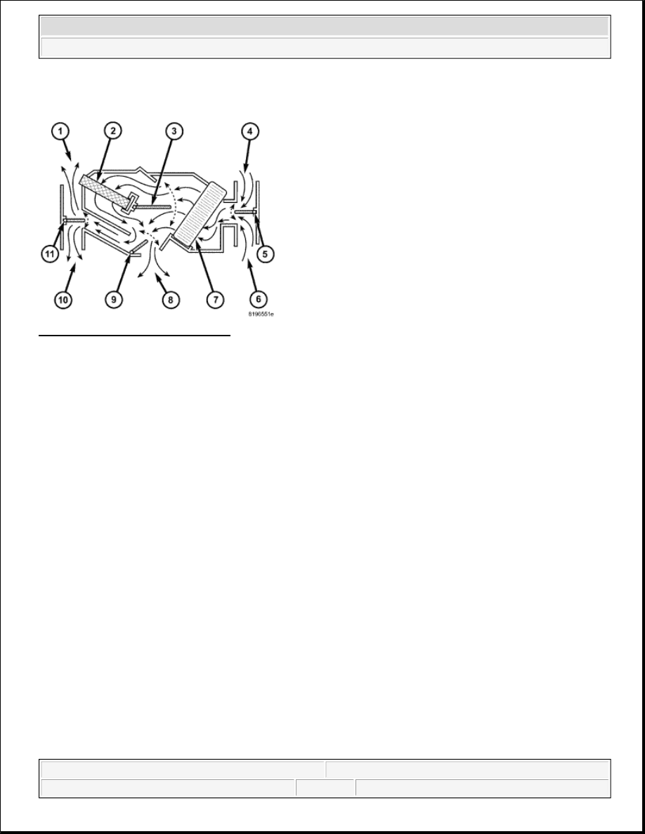
Fig. 2: Blend Air System Schematic 
Courtesy of CHRYSLER LLC 

The heating-A/C system pulls outside (ambient) air through the fresh air intake (4) located at the cowl panel at 
the base of the windshield and into the air inlet housing above the heating, ventilation and air conditioning 
(HVAC) housing and passes through the A/C evaporator (7). Air flow is then directed either through or around 
the heater core (2). This is done by adjusting the position of the blend-air door (3) with the temperature control 
located on the A/C-heater control in the instrument panel. Air flow is then directed out the floor outlet (8), 
instrument panel outlet (10) or the defroster outlet (1) in various combinations by adjusting the position of the 
mode-air doors (9 and 11) using the mode control located on the A/C-heater control. The temperature and mode 
control uses electrical actuators to operate the air doors. 

The velocity of the air flow out of the outlets can be adjusted with the blower speed control located on the A/C-
heater control. 

The fresh air intake can be shut off by pressing the Recirculation button on the A/C-heater control. This will 
operate the electrically actuated recirculation-air door (5), which closes off the fresh air intake. With the fresh 
air intake closed, the conditioned air within the vehicle is pulled back into the HVAC housing through the 
recirculation air intake (6). 

The A/C compressor can be engaged by pressing the A/C (snowflake) button on the A/C-heater control when 
the mode control is set in any floor to instrument panel position. The A/C compressor will automatically engage 
when the mode control is set in any Mix to Defrost position. This is done to help reduce fogging of the front 
windows by removing humidity from the conditioned air prior to it coming into contact with the windows. 

The defroster outlet receives airflow from the HVAC housing through the molded plastic defroster duct. The 
airflow from the defroster outlet is directed by fixed vanes in the defroster outlet grille and cannot be adjusted.

NOTE:

Typical blend-air type HVAC system shown.


2007 Dodge Nitro R/T 

2007 HVAC Heating & Air Conditioning - Service Information - Nitro


The side window demister outlets receive airflow from the HVAC housing through the defroster duct and 
molded plastic demister ducts which are integral to the instrument panel. The airflow from the side window 
demister outlets is directed by fixed vanes in the demister outlet grilles and cannot be adjusted. The demisters 
direct air from the HVAC housing through the outlets located on the top corners of the instrument panel. The 
demisters operate when the mode control is positioned in the floor-defrost and defrost-only settings. Some air 
may be noticeable from the demister outlets when the mode control is in the bi-level to floor positions. 

The panel outlets receive airflow from the HVAC housing through the center panel duct and the two molded 
plastic panel ducts, which are integral to the instrument panel. The two end ducts direct airflow to the left and 
right instrument panel outlets, while the center panel duct directs airflow to the two center panel outlets. Each of 
these outlets can be individually adjusted to direct the flow of air. 

The floor outlets receive airflow from the HVAC housing through the floor distribution ducts. The front floor 
outlets are integral to the molded plastic floor ducts, which are secured to the sides of the HVAC housing. The 
floor outlets cannot be adjusted. 

This A/C system uses an A/C expansion valve to meter the flow of refrigerant to the A/C evaporator. The A/C 
evaporator cools and dehumidifies the incoming air prior to blending it with the heated air. To maintain 
minimum evaporator temperatures and prevent evaporator freezing, an evaporator temperature sensor is used. 
The sensor is located downstream of the evaporator and supplies an evaporator temperature signal to the A/C-
heater control. 

DIAGNOSIS AND TESTING 

A/C PERFORMANCE 

The A/C system is designed to provide the passenger compartment with low temperature and low humidity air. 
The A/C evaporator, located in the HVAC housing is cooled to temperatures near the freezing point. As warm 
damp air passes over the fins of the A/C evaporator, the air transfers its heat to the refrigerant in the evaporator 
coils and the moisture in the air condenses on the evaporator fins. During periods of high heat and humidity, an 
A/C system will be more effective in the Recirculation mode (max-A/C). With the system in the Recirculation 
mode, only air from the passenger compartment passes through the A/C evaporator. As the passenger 
compartment air dehumidifies, the A/C system performance levels rise. 

Humidity has an important bearing on the temperature of the air delivered to the interior of the vehicle. It is 
important to understand the effect that humidity has on the performance of the A/C system. When humidity is 

NOTE:

It is important to keep the air intake opening clear of debris. Leaf particles and 
other debris that is small enough to pass through the cowl opening screen can 
accumulate within the HVAC housing. The closed, warm, damp and dark 
environment created within the housing is ideal for the growth of certain molds, 
mildews and other fungi. Any accumulation of decaying plant matter provides 
an additional food source for fungal spores, which enter the housing with the 
fresh intake-air. Excess debris, as well as objectionable odors created by 
decaying plant matter and growing fungi can be discharged into the passenger 
compartment during heater-A/C operation if the air intake opening is not kept 
clear of debris.


2007 Dodge Nitro R/T 

2007 HVAC Heating & Air Conditioning - Service Information - Nitro


high, the A/C evaporator has to perform a double duty. It must lower the air temperature, and it must lower the 
temperature of the moisture in the air that condenses on the evaporator fins. Condensing the moisture in the air 
transfers heat energy into the evaporator fins and coils. This reduces the amount of heat the A/C evaporator can 
absorb from the air. High humidity greatly reduces the ability of the A/C evaporator to lower the temperature of 
the air. 

However, evaporator capacity used to reduce the amount of moisture in the air is not wasted. Wringing some of 
the moisture out of the air entering the vehicle adds to the comfort of the passengers. Although, an owner may 
expect too much from their A/C system on humid days. A performance test is the best way to determine 
whether the system is performing up to design standards. This test also provides valuable clues as to the 
possible cause of trouble with the A/C system. The ambient air temperature in the location where the vehicle 
will be tested must be a minimum of 21°C (70°F) for this test. 

A/C PERFORMANCE TEST 

1. Check for diagnostic trouble codes using a scan tool. If no DTCs are found in the powertrain control 

module (PCM) or engine control module (ECM), depending on engine application, go to step 2  

2. Connect a tachometer and a manifold gauge set or an A/C recycling/charging station.  

3. Operate the heating-A/C system under the following conditions. 

Engine at 1,000 RPM at operating temperature  

Door or windows open  

Transmission in Park or Neutral with parking brake set (depending on transmission application)  

A/C-heater controls set to Recirculation mode (max-A/C), full cool, panel mode, high blower and 
with A/C compressor engaged. If the A/C compressor does not engage, see the A/C System 
Diagnosis chart.  

4. Insert a thermometer in the driver side center panel air outlet and operate the vehicle a minimum of ten 

minutes to allow the thermometer temperature to stabilize. 

WARNING:

Refer to the applicable warnings and cautions for this system before 
performing the following operation. See WARNING, and CAUTION. Failure 
to follow the warnings and cautions could result in possible serious or 
fatal injury.

CAUTION: The use of an A/C recycling/charging station for purposes of determining 

the actual charge level of an A/C system is not recommend. Service 
recycling/charging stations do not reflect the correct amount of refrigerant 
charge in the A/C system after a single "reclaim" cycle. Tests have shown 
that it takes up to 3 or 4 "reclaim" cycles to remove all of the refrigerant 
charge. Use only the following procedure for determining the proper 
charge level.

NOTE:

When connecting the service equipment coupling to the line fitting, verify that 
the valve of the coupling is fully closed. This will reduce the amount of effort 
required to make the connection.


2007 Dodge Nitro R/T 

2007 HVAC Heating & Air Conditioning - Service Information - Nitro


5. With the A/C compressor clutch engaged, compare the air temperature at the center panel outlet and the 

A/C compressor discharge pressure (high side) to the A/C Performance Temperature and Pressure chart. 
The compressor clutch may cycle, depending upon the ambient temperature and humidity. If the clutch 
cycles, use the readings obtained before the clutch disengaged. 

A/C PERFORMANCE TEMPERATURE AND PRESSURE 

6. If the air outlet temperature fails to meet the specifications in the A/C Performance Temperature and 

Pressure chart, or if the A/C compressor discharge pressure is high, refer to the A/C System Diagnosis 
chart.  

A/C SYSTEM DIAGNOSIS 

Ambient Air 
Temperature
 

21°C 

(70°F)

27°C 

(80°F)

32°C 

(90°F)

38°C 

(100°F)

43°C 

(110°F)

Air Temperature 
at Center Panel 
Outlet
 

7°C 

(45°F)

7°C 

(45°F)

13°C 

(55°F)

13°C 

(55°F)

18°C 

(64°F)

Compressor 
Inlet Pressure at 
Service Port 
(Low Side)
 

138 to 207 

kPa 

(20 to 30 

psi)

172 to 241 

kPa 

(25 to 35 

psi)

207 to 276 

kPa 

(30 to 40 

psi)

241 to 310 

kPa 

(35 to 45 

psi)

276 to 345 

kPa 

(40 to 50 

psi)

Condenser 
Outlet Pressure 
at Service Port 
(High Side)
 

1034 to 

1724 kPa 

(150 to 250 

psi)

1379 to 

2068 kPa

(200 to 300 

psi)

1724 to 

2413 kPa

(250 to 350 

psi)

1999 to 

2689 kPa

(290 to 390 

psi)

2413 to 

2965 kPa 

(350 to 430 

psi)

Condition

Possible Causes

Correction

Rapid A/C clutch cycling 
(ten or more cycles per 
minute).

1. Low refrigerant system 
charge. 

1. See REFRIGERANT SYSTEM LEAKS
Test the refrigerant system for leaks. Repair, 
evacuate and charge the refrigerant system as 
required. 

Equal pressures, but the A/C 
clutch does not engage.

1. No refrigerant in the 
refrigerant system. 

1. See REFRIGERANT SYSTEM LEAKS
Test the refrigerant system for leaks. Repair, 
evacuate and charge the refrigerant system as 
required. 


2. Open fuse. 

2. Check the fuses in the power distribution 
center and the junction block. Repair the 
shorted circuit or component and replace the 
fuses as required. 


3. Inoperative A/C clutch 
field coil. 

3. See A/C Compressor Clutch in this group. 
Test the A/C clutch field coil and replace as 
required. 


4. Inoperative A/C clutch 
relay. 

4. See CLUTCH-A/C COMPRESSOR . Test 
the A/C clutch relay and relay circuits. Repair 
the circuits or replace the relay as required. 


5. Improperly installed or 

5. See TRANSDUCER-A/C PRESSURE


2007 Dodge Nitro R/T 

2007 HVAC Heating & Air Conditioning - Service Information - Nitro


Content   ..  727  728  729  730   ..