Dodge Nitro. Manual - part 110


  Index      Dodge     Dodge Nitro - service repair manual 2007 year


Search            


Content   ..  108  109  110  111   ..


Dodge Nitro. Manual - part 110


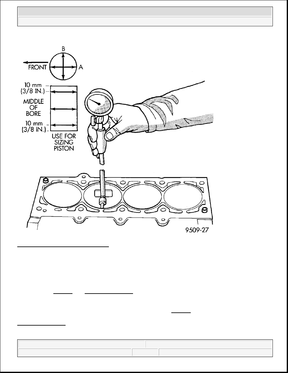
Fig. 175: Cylinder Bore Measurement 
Courtesy of CHRYSLER LLC 

The cylinder walls should be checked for out-of-round and taper with Tool C119 cylinder bore gauge, or 
equivalent. See Fig. 175. See SPECIFICATIONS. If the cylinder walls are badly scuffed or scored, the 
cylinder block should be replaced, and new pistons and rings fitted.  

Measure the cylinder bore at three levels in directions A and B. See Fig. 175. Top measurement should be 10 
mm (3/8 in.) down and bottom measurement should be 10 mm (3/8 in.) up from bottom of bore. See 
SPECIFICATIONS.  

BEARING -CONNECTING ROD 

NOTE:

The cylinder bores should be measured at normal room temperature, 21°C (70°
F).


2007 Dodge Nitro R/T 

2007 ENGINE 4.0L - Service Information - Nitro


STANDARD PROCEDURE 

CONNECTING RODS AND BEARINGS 

Fig. 176: Connecting Rod Bearing Clearance 
Courtesy of CHRYSLER LLC 

The bearing shells must be installed with the tangs inserted into the machined grooves in the rods and caps. 

CAUTION: The bearing caps are not interchangeable and should be paint marked or 

scribed at removal to insure correct assembly. DO NOT use a metal stamp.


2007 Dodge Nitro R/T 

2007 ENGINE 4.0L - Service Information - Nitro


Install cap with the tangs on the same side as the rod.

Fit all rods on one bank until complete. 

Limits of out-of-round on any crankshaft journals should be held to 0.008 mm (0.0003 in.). Bearings are 
available in standard, 0.025 mm (0.001 in.), and 0.254 mm (0.010 in.) undersizes. Install the bearings in pairs. 
Do not use a new bearing half with an old bearing half. Do not file the rods or bearing caps.
  

1. For measuring main bearing clearance and connecting rod bearing clearance use plastigage. See Fig. 176

For more information on using plastigage. See STANDARD PROCEDURE. Refer to Engine 
Specifications for bearing clearance specifications . See SPECIFICATIONS.  

CONNECTING ROD BOLTS 

Fig. 177: Examining Connecting Rod Bolts For Stretching 
Courtesy of CHRYSLER LLC 

1. Examine connecting rod bolts for stretching (1). Stretching (1) can be checked by holding a scale or 

straight edge against the threads. If all the threads do not contact the scale the bolt must be replaced.  

2. Before installing the bolts the threads should be cleaned and inspected. 

NOTE:

The rod bearing bolts should be examined before reuse. If the threads are 
necked down the bolts must be replaced. See Fig. 177.

1 - STRETCHED BOLT
2 - THREADS ARE NOT STRAIGHT ON LINE
3 - THREADS ARE STRAIGHT ON LINE
4 - UNSTRETCHED BOLT


2007 Dodge Nitro R/T 

2007 ENGINE 4.0L - Service Information - Nitro


3. Install clean bolts finger tight. Then alternately torque each bolt to assemble the cap properly.  

4. Tighten the connecting rod cap bolts to specification. See SPECIFICATIONS.  

CONNECTING ROD SIDE CLEARANCE 

Fig. 178: Connecting Rod Side Clearance Measuring 
Courtesy of CHRYSLER LLC 

1. Mount a dial indicator to a stationary point on engine. Locate probe perpendicular to and resting against 

the connecting rod cap being checked. Move connecting rod all the way to rear of its travel. Zero the dial 
indicator. Move connecting rod forward to limit of travel and read the dial indicator. See Fig. 178
Compare measurement to specification listed in engine specifications. See SPECIFICATIONS. Repeat 
procedure for each connecting rod. Turn crankshaft for connecting rod accessibility.  

CRANKSHAFT 

DESCRIPTION 

CRANKSHAFT 

The crankshaft is constructed of a forged micro alloy steel. A six throw, nine counterweight crankshaft is 


2007 Dodge Nitro R/T 

2007 ENGINE 4.0L - Service Information - Nitro


Content   ..  108  109  110  111   ..