Dodge Durango (HB). Manual - part 1239


  Index      Dodge     Dodge Durango (HB) - service repair manual 2005 year


Search            


Content   ..  1237  1238  1239  1240   ..


Dodge Durango (HB). Manual - part 1239


P0562-BATTERY VOLTAGE LOW (CONTINUED)

5.

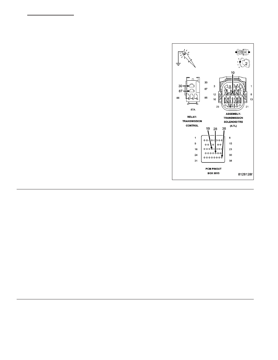
CHECKING THE (T16) TRANSMISSION CONTROL RELAY OUTPUT CIRCUIT

Turn the ignition off to the lock position.

NOTE: Check connectors - Clean/repair as necessary.
Connect a jumper wire between (A104) Fused B+ circuit and the (T16)
Transmission Control Relay Output circuit in the Transmission Control
Relay connector.

Ignition on, engine not running.

Using a 12-volt test light connected to ground, check all (T16) Trans-
mission Control Relay Output circuits at the appropriate terminals of
Miller tool #8815.

Does the test light illuminate brightly?

Yes

>> Go To 6

No

>> Repair the (T16) Transmission Control Relay Output circuit

for an open or high resistance.

Perform 45RFE/545RFE TRANSMISSION VERIFICATION
TEST - VER 1.

6.

TRANSMISSION CONTROL RELAY

Turn the ignition off to the lock position.

Reconnect all previously disconnected connectors.

Install a substitute Relay in place of the Transmission Control Relay.

Start the engine.

Using a voltmeter, measure the vehicles battery voltage.

With the scan tool, monitor the Transmission Switched Battery Voltage.

Compare the scan tool Transmission Switched Battery voltage to the actual battery voltage reading on the voltmeter.

Is the scan tool voltage within 1.0 volt of the battery voltage?

Yes

>> Replace the Transmission Control Relay.

Perform 45RFE/545RFE TRANSMISSION VERIFICATION TEST - VER 1.

No

>> Using the schematics as a guide, check the Powertrain Control Module (PCM) terminals for corrosion,

damage, or terminal push out. Pay particular attention to all power and ground circuits. If no problems
are found, replace the PCM per the Service Information. With the scan tool, perform QUICK LEARN.

Perform 45RFE/545RFE TRANSMISSION VERIFICATION TEST - VER 1.

HB

AUTOMATIC TRANSMISSION 545RFE - ELECTRICAL DIAGNOSTICS

21 - 361

P0562-BATTERY VOLTAGE LOW (CONTINUED)

7.

INTERMITTENT WIRING AND CONNECTORS

The conditions necessary to set this DTC are not present at this time.

Using the schematics as a guide, inspect the wiring and connectors specific to this circuit.

Wiggle the wires while checking for shorted and open circuits.

With the scan tool, check the EATX DTC EVENT DATA to help identify the conditions in which the DTC was set.

Where there any problems found?

Yes

>> Repair as necessary.

Perform 45RFE/545RFE TRANSMISSION VERIFICATION TEST - VER 1.

No

>> Test Complete.

21 - 362

AUTOMATIC TRANSMISSION 545RFE - ELECTRICAL DIAGNOSTICS

HB

P0602-CONTROL MODULE PROGRAMMING ERROR/NOT PROGRAMMED

For the Transmission circuit diagram (Refer to 21 - TRANSMISSION/TRANSAXLE/AUTOMATIC - 45RFE/545RFE -
SCHEMATICS AND DIAGRAMS)

For a complete wiring diagram Refer to Section 8W

When Monitored:
Check for generic software is made at power-up

Set Condition:
If genic software is found , the MIL will light immediately. This DTC is designed to signal the technician that the
controller still has generic software installed.

Possible Causes

PCM - PROGRAMMING ERROR

Always perform the Pre-Diagnostic Troubleshooting procedure before proceeding. (Refer to 21 - TRANSMIS-
SION/TRANSAXLE/AUTOMATIC - 45RFE/545RFE - DIAGNOSIS AND TESTING)

Theory of Operation

The controller is programmed during manufacturing with generic software to facilitate testing. This software does not
have the proper calibrations to control a transmission in a vehicle. The check for generic software is made at power-
up. If generic software is found , the MIL will light immediately and the MIL will stay on even if the fault is cleared,
until the proper software is installed. Note: Transmission will be placed in limp-in mode.

Diagnostic Test

1.

CONTROL MODULE PROGRAMMING ERROR

NOTE: Controller is programmed with generic software and will not allow the correct vehicle Powertrain
management.
With the scan tool.

Record the vehicles controller part number.

Select Use Controller Part Number under the Flash Tab.

Flash the controller with the correct software.

Verify the controller flashed successfully.

Test Complete

Perform 45RFE/545RFE TRANSMISSION VERIFICATION TEST - VER 1. Perform Quick Learn Proce-
dure per the Service Information.

HB

AUTOMATIC TRANSMISSION 545RFE - ELECTRICAL DIAGNOSTICS

21 - 363

P0604-INTERNAL CONTROL MODULE RAM

For the Transmission circuit diagram (Refer to 21 - TRANSMISSION/TRANSAXLE/AUTOMATIC - 45RFE/545RFE -
SCHEMATICS AND DIAGRAMS).

For a complete wiring diagram Refer to Section 8W.

When Monitored:
One time after the controller is reset (ignition turned to the RUN position).

Set Condition:
Whenever the Powertrain Control Module (PCM) detects an internal controller problem.

Possible Causes

POWER OR GROUND CIRCUIT

POWERTRAIN CONTROL MODULE

Always perform the Pre-Diagnostic Troubleshooting procedure before proceeding. (Refer to 21 - TRANSMIS-
SION/TRANSAXLE/AUTOMATIC - 45RFE/545RFE - DIAGNOSIS AND TESTING).

Theory of Operation

After the controller is reset (ignition turned to the RUN position), the microprocessor checks the integrity of each
RAM location by writing to it and reading back from it. The read value should be same as value written.

Diagnostic Test

1.

CHECK WIRING AND CONNECTORS FOR INTERMITTENT OPERATION

Using the schematics as a guide, check the Powertrain Control Module (PCM) terminals for corrosion, damage, or
terminal push out. Pay particular attention to all power and ground circuits.

NOTE: Due to the integration of the Powertrain and Transmission Control Modules, the transmission part of
the PCM has it’s own specific power and ground circuits.
Wiggle the wires while checking for shorted and open circuits.

Check for any Service Bulletins that may apply.

Were there any problems found?

Yes

>> Repair the power and/or ground circuits to the PCM and Transmission Control Relay as necessary.

Perform 45RFE/545RFE TRANSMISSION VERIFICATION TEST - VER 1.

No

>> Replace the PCM per the Service Information. With the scan tool, perform QUICK LEARN.

Perform 45RFE/545RFE TRANSMISSION VERIFICATION TEST - VER 1.

21 - 364

AUTOMATIC TRANSMISSION 545RFE - ELECTRICAL DIAGNOSTICS

HB


Content   ..  1237  1238  1239  1240   ..