Dodge Durango (DN). Manual - part 423


  Index      Dodge     Dodge Durango (DN) - service repair manual 2000 year


Search            


Content   ..  421  422  423  424   ..


Dodge Durango (DN). Manual - part 423


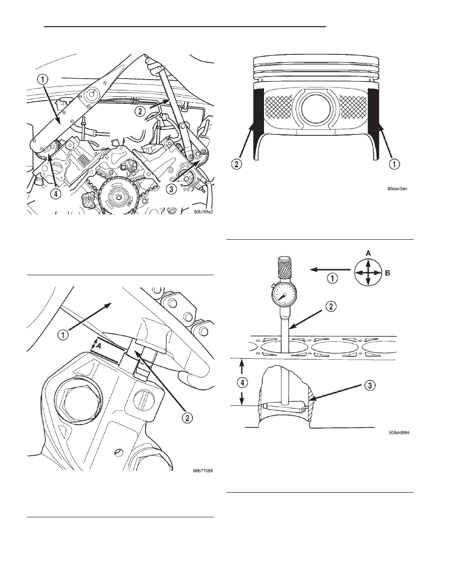
Fig. 16 Camshaft Sprocket Installation—Right

Cylinder Head

1 – TORQUE WRENCH
2 – SPECIAL TOOL 6958 WITH ADAPTER PINS 8346
3 – LEFT CAMSHAFT SPROCKET
4 – RIGHT CAMSHAFT SPROCKET

Fig. 17 Measuring Secondary Timing Chains For

Stretch

1 – SECONDARY TENSIONER ARM
2 – SECONDARY CHAIN TENSIONER PISTON

Fig. 18 Moly Coated Piston

1 – MOLY COATED
2 – MOLY COATED

Fig. 19 Bore Gauge—Typical

1 – FRONT
2 – BORE GAUGE
3 – CYLINDER BORE
4 – 49.5 MM

(1–15/16 in)

DN

4.7L ENGINE

9 - 23

SERVICE PROCEDURES (Continued)

PISTON RINGS—FITTING

RING END GAP
Before reinstalling used rings or installing new

rings, the ring clearances must be checked.

(1) Wipe the cylinder bore clean.
(2) Insert the ring in the cylinder bore.

NOTE: The ring gap measurement must be made
with the ring positioned at least 12mm (0.50 inch.)
from bottom of cylinder bore.

(3) Using a piston, to ensure that the ring is

squared in the cylinder bore, slide the ring downward
into the cylinder.

(4) Using a feeler gauge check the ring end gap

(Fig. 20). Replace any rings not within specification.

PISTON RING SIDE CLEARANCE

NOTE: Make sure the piston ring grooves are clean
and free of nicks and burrs.

(5) Measure the ring side clearance as shown (Fig.

21) make sure the feeler gauge fits snugly between
the ring land and the ring. Replace any ring not
within specification.

(6) Rotate the ring around the piston, the ring

must rotate in the groove with out binding.

EARLY BUILD

(7) The No. 1 and No. 2 piston rings have a differ-

ent cross section. Ensure No. 2 ring is installed with
manufacturers I.D. mark (Dot) facing up, towards top
of the piston.

LATE BUILD

The No. 1 and No. 2 piston rings have a different

cross section. Ensure No. 2 ring is installed with
manufacturers I.D. mark (Dot) facing up, towards top
of the piston. On late build engines the piston top
ring groove and crown are not anodized therefore,
the No. 1 piston ring is coated with an anti-friction
coating. Care must be used to ensure that when

installing piston rings on late build engines that the
correct No. 1 piston ring be installed, failure to use
the correct piston ring can cause severe damage to
the piston and/or cylinder block.

Fig. 20 Ring End Gap Measurement—Typical

1 – FEELER GAUGE

Fig. 21 Measuring Piston Ring Side Clearance

1 – FEELER GAUGE

PISTON RING SPECIFICATION CHART

Ring Position

Groove

Maximum

Clearance

Clearance

Upper Ring

.051-.094mm

0.11mm

(0.0020-.0037

in.)

(0.004 in.)

Intermediate

Ring

0.04-0.08mm

0.10mm

(0.0016-0.0031

in.)

(0.004 in.)

Oil Control Ring

.019-.229mm

.25mm

(Steel Rails)

(.0007-.0090 in.)

(0.010 in.)

Ring Position

Ring Gap

Wear Limit

Upper Ring

0.20-0.36mm

0.40mm

(0.008-0.014 in.)

(0.0016in.)

Intermediate

Ring

0.37-0.63mm

0.71mm

(0.014-0.025 in.)

(0.028in.)

Oil Control Ring

0.025-0.76mm

1.52mm

(Steel Rail)

(0.010- 0.030

in.)

(0.060in.)

9 - 24

4.7L ENGINE

DN

SERVICE PROCEDURES (Continued)

2000 DN Service Manual
Publication No. 81-370-0016
TSB 26-12-99

December, 1999

NOTE: Piston rings are installed in the following
order:

Oil ring expander.

Upper oil ring side rail.

Lower oil ring side rail.

No. 2 Intermediate piston ring.

No. 1 Upper piston ring.

(8) Install the oil ring expander.
(9) Install upper side rail (Fig. 22) by placing one

end between the piston ring groove and the expander
ring. Hold end firmly and press down the portion to
be installed until side rail is in position. Repeat this
step for the lower side rail.

(10) Install No. 2 intermediate piston ring using a

piston ring installer (Fig. 23).

(11) Install No. 1 upper piston ring using a piston

ring installer (Fig. 23).

(12) Position piston ring end gaps as shown in

(Fig. 24). It is important that expander ring gap is at
least 45° from the side rail gaps, but not on the pis-
ton pin center or on the thrust direction.

CONNECTING ROD BEARINGS—FITTING

Inspect the connecting rod bearings for scoring and

bent alignment tabs (Fig. 25) (Fig. 26). Check the
bearings for normal wear patterns, scoring, grooving,
fatigue and pitting (Fig. 27). Replace any bearing
that shows abnormal wear.

Inspect the connecting rod journals for signs of

scoring, nicks and burrs.

Misaligned or bent connecting rods can cause

abnormal wear on pistons, piston rings, cylinder
walls, connecting rod bearings and crankshaft con-
necting rod journals. If wear patterns or damage to
any of these components indicate the probability of a
misaligned connecting rod, inspect it for correct rod

alignment. Replace misaligned, bent or twisted con-
necting rods.

(1) Wipe the oil from the connecting rod journal.
(2) Lubricate the upper bearing insert and install

in connecting rod.

(3) Use piston ring compressor and Guide Pins

Special Tool 8507 (Fig. 28) to install the rod and pis-
ton assemblies. The oil slinger slots in the rods must
face front of the engine. The “F”’s near the piston
wrist pin bore should point to the front of the engine.

(4) Install the lower bearing insert in the bearing

cap. The lower insert must be dry. Place strip of Plas-
tigage across full width of the lower insert at the cen-
ter of bearing cap. Plastigage must not crumble in
use. If brittle, obtain fresh stock.

Fig. 22 Side Rail—Installation

1 – SIDE RAIL END

Fig. 23 Upper and Intermediate Rings—Installation

Fig. 24 Piston Ring End Gap Position

1 – SIDE RAIL UPPER
2 – NO. 1 RING GAP
3 – PISTON PIN
4 – SIDE RAIL LOWER
5 – NO. 2 RING GAP AND SPACER EXPANDER GAP

DN

4.7L ENGINE

9 - 25

SERVICE PROCEDURES (Continued)

(5) Install bearing cap and connecting rod on the

journal and tighten bolts to 27 N·m (20 ft. lbs.) plus a
90° turn. DO NOT rotate crankshaft. Plastigage will
smear, resulting in inaccurate indication.

(6) Remove the bearing cap and determine amount

of bearing-to-journal clearance by measuring the
width of compressed Plastigage (Fig. 29). Refer to
Engine Specifications for the proper clearance. Plas-
tigage

should

indicate

the

same

clearance

across the entire width of the insert. If the
clearance varies, it may be caused by either a
tapered journal, bent connecting rod or foreign
material trapped between the insert and cap or
rod.

(7) If the correct clearance is indicated, replace-

ment of the bearing inserts is not necessary. Remove
the Plastigage from crankshaft journal and bearing
insert. Proceed with installation.

(8) If

bearing-to-journal

clearance

exceeds

the

specification, determin which services bearing set to
use the bearing sizes are as follows:

Fig. 25 Connecting Rod Bearing Inspection

1 – UPPER BEARING HALF
2 – MATING EDGES
3 – GROOVES CAUSED BY ROD BOLTS SCRATCHING

JOURNAL DURING INSTALLATION

4 – WEAR PATTERN — ALWAYS GREATER ON UPPER

BEARING

5 – LOWER BEARING HALF

Fig. 26 Locking Tab Inspection

1 – ABNORMAL CONTACT AREA CAUSED BY LOCKING TABS

NOT FULLY SEATED OR BEING BENT

Fig. 27 Scoring Caused by Insufficient Lubrication

or by Damaged Crankshaft Pin Journal

Fig. 28 Piston and Connecting Rod—Installation

1 – “F” TOWARD FRONT OF ENGINE
2 – OIL SLINGER SLOT
3 – RING COMPRESSOR
4 – SPECIAL TOOL 8507

9 - 26

4.7L ENGINE

DN

SERVICE PROCEDURES (Continued)


Content   ..  421  422  423  424   ..