Dodge Durango (DN). Manual - part 315
 

  Index      Dodge     Dodge Durango (DN) - service repair manual 2000 year


Search            


Content   ..  313  314  315  316   ..


Dodge Durango (DN). Manual - part 315


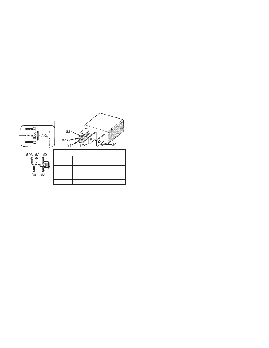
Remove the relay (Fig. 3) from the PDC, JB or the

relay and fuse block as described in this group to
perform the following tests:

(1) A relay in the de-energized position should

have continuity between terminals 87A and 30, and
no continuity between terminals 87 and 30. If OK, go
to Step 2. If not OK, replace the faulty relay.

(2) Resistance between terminals 85 and 86 (elec-

tromagnet) should be 75

6 5 ohms. If OK, go to Step

3. If not OK, replace the faulty relay.

(3) Connect a battery to terminals 85 and 86.

There should now be continuity between terminals
30 and 87, and no continuity between terminals 87A
and 30. If OK, test the relay circuits. If not OK,
replace the faulty relay.

SERVICE PROCEDURES

REMOTE KEYLESS ENTRY TRANSMITTER
BATTERY REPLACEMENT

The Remote Keyless Entry (RKE) transmitter case

snaps open and shut for battery access. To replace
the RKE transmitter batteries:

(1) Using a trim stick or another suitable wide

flat-bladed tool, gently pry at the center seam of the
transmitter case halves near the key ring until the
two halves unsnap.

(2) Lift the back half of the transmitter case off of

the transmitter.

(3) Remove the two batteries from the transmitter.
(4) Replace the two batteries with new Duracell

DL2016, or their equivalent. Be certain that the bat-
teries are installed with their polarity correctly ori-
ented.

(5) Align the two transmitter case halves with

each other, and squeeze them firmly together until
they snap back into place.

REMOTE KEYLESS ENTRY TRANSMITTER
PROGRAMMING

To program the Remote Keyless Entry (RKE)

transmitter access codes into the RKE receiver in the
Central Timer Module (CTM) requires the use of a
DRB scan tool. Refer to the proper Diagnostic Proce-
dures manual for more information.

REMOVAL AND INSTALLATION

POWER LOCK SWITCH

DRIVER SIDE FRONT DOOR

(1) Disconnect and isolate the battery negative

cable.

(2) Remove the trim panel from the inside of the

driver side front door. Refer to Group 23 - Body for
the procedures.

(3) From the back side of the trim panel, remove

the screws that secure the power window and lock
switch unit to the switch bezel in the door trim panel
opening.

(4) Remove the power window and lock switch and

the switch bezel from the door trim panel.

(5) Reverse the removal procedures to install.

Tighten the mounting screws to 2.2 N·m (20 in. lbs.).

PASSENGER SIDE FRONT DOOR

(1) Disconnect and isolate the battery negative

cable.

(2) Remove the trim panel from the inside of the

passenger side front door. Refer to Group 23 - Body
for the procedures.

(3) With a small thin-bladed screwdriver, gently

pry the snap clips at the sides of the power lock
switch receptacle on the back of the door trim panel
switch bezel and pull the switch out of the receptacle.

(4) Reverse the removal procedures to install. Be

certain that both of the switch snap retainers in the
receptacle on the back of the door trim panel switch
bezel are fully engaged.

POWER LOCK MOTOR

DOOR

The power lock motor is integral to the door latch

unit. If the power lock motor is faulty or damaged,
the entire door latch unit must be replaced. Refer to
Group 23 - Body for the door latch service proce-
dures.

LIFTGATE

(1) Disconnect and isolate the battery negative

cable.

TERMINAL LEGEND

NUMBER

IDENTIFICATION

30

COMMON FEED

85

COIL GROUND

86

COIL BATTERY

87

NORMALLY OPEN

87A

NORMALLY CLOSED

Fig. 3 Relay Terminals

8P - 8

POWER LOCK SYSTEMS

DN

DIAGNOSIS AND TESTING (Continued)

(2) Remove the trim panel from the inner liftgate

panel. Refer to Group 23 - Body for the procedures.

(3) Remove the two screws that secure the power

lock motor to the liftgate inner panel (Fig. 4).

(4) Pull the power lock motor out through the

access hole in the liftgate inner panel far enough to
access and unplug the wire harness connector.

(5) Lower the power lock motor far enough to

access and disengage the link from the liftgate latch
clip.

(6) Remove the power lock motor from the liftgate.
(7) Reverse the removal procedures to install.

Tighten the mounting screws to 3.3 N·m (30 in. lbs.).

DRIVER UNLOCK RELAY

WARNING: ON VEHICLES EQUIPPED WITH AIR-
BAGS,

REFER

TO

GROUP

8M

-

PASSIVE

RESTRAINT SYSTEMS BEFORE ATTEMPTING ANY
STEERING

WHEEL,

STEERING

COLUMN,

OR

INSTRUMENT PANEL COMPONENT DIAGNOSIS OR
SERVICE. FAILURE TO TAKE THE PROPER PRE-
CAUTIONS COULD RESULT IN ACCIDENTAL AIR-
BAG DEPLOYMENT AND POSSIBLE PERSONAL
INJURY.

(1) Disconnect and isolate the battery negative

cable.

(2) Remove the steering column opening cover and

knee blocker from the instrument panel. Refer to
Steering Column Opening Cover and Knee Blocker in
the Removal and Installation section of Group 8E -
Instrument Panel Systems for the procedures.

(3) Reach through the outboard side of the steer-

ing column opening in the instrument panel to access

the relay and fuse block on the back of the junction
block (Fig. 5).

(4) Unplug the driver unlock relay from the relay

and fuse block.

(5) Install the driver unlock relay by aligning the

relay terminals with the cavities in the relay and
fuse block and pushing the relay firmly into place.

(6) Connect the battery negative cable.
(7) Test the relay operation.
(8) Reverse the remaining removal procedures to

complete the installation.

HEADLAMP RELAY

WARNING: ON VEHICLES EQUIPPED WITH AIR-
BAGS,

REFER

TO

GROUP

8M

-

PASSIVE

RESTRAINT SYSTEMS BEFORE ATTEMPTING ANY
STEERING

WHEEL,

STEERING

COLUMN,

OR

INSTRUMENT PANEL COMPONENT DIAGNOSIS OR
SERVICE. FAILURE TO TAKE THE PROPER PRE-
CAUTIONS COULD RESULT IN ACCIDENTAL AIR-
BAG DEPLOYMENT AND POSSIBLE PERSONAL
INJURY.

(1) Disconnect and isolate the battery negative

cable.

(2) Remove the cover from the Power Distribution

Center (PDC) (Fig. 6).

(3) Refer to the label on the PDC for headlamp

relay identification and location.

(4) Unplug the headlamp relay from the PDC.
(5) Install the headlamp relay by aligning the

relay terminals with the cavities in the PDC and
pushing the relay firmly into place.

Fig. 4 Liftgate Power Lock Motor Remove/Install

1 – WIRE HARNESS CONNECTOR
2 – SCREW
3 – MOTOR
4 – LINK

Fig. 5 Relay and Fuse Block

1 – JUNCTION BLOCK
2 – RELAY AND FUSE BLOCK

DN

POWER LOCK SYSTEMS

8P - 9

REMOVAL AND INSTALLATION (Continued)

(6) Install the PDC cover.
(7) Connect the battery negative cable.
(8) Test the relay operation.

HORN RELAY

(1) Disconnect and isolate the battery negative

cable.

(2) Remove the fuse access panel from the left end

of the instrument panel (Fig. 7).

(3) Refer to the label on the inside of the fuse

access panel for horn relay identification and loca-
tion.

(4) Unplug the horn relay from the Junction Block

(JB).

(5) Install the horn relay by aligning the relay ter-

minals with the cavities in the JB and pushing the
relay firmly into place.

(6) Install the fuse access panel.
(7) Connect the battery negative cable.
(8) Test the relay operation.

Fig. 6 Power Distribution Center

1 – CLIP
2 – BATTERY
3 – TRAY
4 – NEGATIVE CABLE
5 – POSITIVE CABLE
6 – CLIP
7 – FENDER INNER SHIELD
8 – POWER DISTRIBUTION CENTER

Fig. 7 Horn Relay Remove/Install

1 – INSTRUMENT PANEL
2 – JUNCTION BLOCK
3 – FUSE ACCESS PANEL
4 – HORN RELAY

8P - 10

POWER LOCK SYSTEMS

DN

REMOVAL AND INSTALLATION (Continued)

VEHICLE THEFT/SECURITY SYSTEMS

TABLE OF CONTENTS

page

page

GENERAL INFORMATION

INTRODUCTION . . . . . . . . . . . . . . . . . . . . . . . . . . 1
VEHICLE THEFT SECURITY SYSTEM. . . . . . . . . . 1
ENABLING. . . . . . . . . . . . . . . . . . . . . . . . . . . . . . . 1
ARMING . . . . . . . . . . . . . . . . . . . . . . . . . . . . . . . . 1
DISARMING . . . . . . . . . . . . . . . . . . . . . . . . . . . . . 2
POWER-UP MODE . . . . . . . . . . . . . . . . . . . . . . . . 2
TAMPER ALERT . . . . . . . . . . . . . . . . . . . . . . . . . . 2

DESCRIPTION AND OPERATION

CENTRAL TIMER MODULE . . . . . . . . . . . . . . . . . 2
DOOR AJAR SWITCH . . . . . . . . . . . . . . . . . . . . . . 3
LIFTGATE AJAR SWITCH . . . . . . . . . . . . . . . . . . . 3
DOOR LOCK CYLINDER SWITCH. . . . . . . . . . . . . 3
LIFTGATE LOCK CYLINDER SWITCH . . . . . . . . . . 3
HEADLAMP RELAY. . . . . . . . . . . . . . . . . . . . . . . . 3

HORN RELAY . . . . . . . . . . . . . . . . . . . . . . . . . . . . 4
SECURITY LAMP . . . . . . . . . . . . . . . . . . . . . . . . . 4

DIAGNOSIS AND TESTING

VEHICLE THEFT SECURITY SYSTEM. . . . . . . . . . 4
DOOR LOCK CYLINDER SWITCH. . . . . . . . . . . . . 4
LIFTGATE LOCK CYLINDER SWITCH . . . . . . . . . . 4
RELAYS. . . . . . . . . . . . . . . . . . . . . . . . . . . . . . . . . 5

REMOVAL AND INSTALLATION

DOOR AJAR SWITCH . . . . . . . . . . . . . . . . . . . . . . 5
LIFTGATE AJAR SWITCH . . . . . . . . . . . . . . . . . . . 5
DOOR LOCK CYLINDER SWITCH. . . . . . . . . . . . . 5
LIFTGATE LOCK CYLINDER SWITCH . . . . . . . . . . 5
HEADLAMP RELAY. . . . . . . . . . . . . . . . . . . . . . . . 6
HORN RELAY . . . . . . . . . . . . . . . . . . . . . . . . . . . . 7

GENERAL INFORMATION

INTRODUCTION

The Vehicle Theft Security System (VTSS) is an

available factory-installed option on this model. Refer
to 8W-39 - Vehicle Theft Security System in Group
8W - Wiring Diagrams for complete circuit descrip-
tions and diagrams.

VEHICLE THEFT SECURITY SYSTEM

The Vehicle Theft Security System (VTSS) is

designed to provide perimeter protection against
unauthorized use or tampering by monitoring the
vehicle doors and the ignition system. If unautho-
rized use or tampering is detected, the system
responds by sounding the horn, flashing the head-
lamps, and providing an engine no-run feature.

Following are general descriptions of the features

and major components of the VTSS. Refer to the
owner’s manual in the vehicle glove box for more
information on the features, use and operation of the
vehicle theft security system.

ENABLING

If the vehicle is so equipped, the Vehicle Theft

Security System (VTSS) feature is enabled in the
high-line Central Timer Module (CTM) before the
vehicle is shipped from the factory. However, if a
vehicle with VTSS requires CTM replacement, the
VTSS feature must be enabled in the new CTM using

a DRB scan tool. Refer to the Vehicle Theft Security
System menu item on the DRB scan tool for the pro-
cedures.

The VTSS engine no-run feature is disabled when

it is shipped from the factory. This is done by pro-
gramming within the Powertrain Control Module
(PCM). The logic in the PCM prevents the VTSS
engine no-run feature from arming until the engine
start counter within the PCM sees twenty engine
starts. The VTSS no-run feature must be enabled
when the vehicle is received from the assembly plant.

Once the VTSS engine no-run feature has been

enabled, it cannot be disabled unless the PCM is
replaced with a new unit. The same VTSS engine no-
run feature enable logic will apply anytime the PCM
is replaced with a new unit.

ARMING

Passive arming of the Vehicle Theft Security Sys-

tem (VTSS) occurs when the vehicle is exited with
the key removed from the ignition switch, the head-
lamps are turned off, and the doors and liftgate are
locked while they are open using the power lock
switch or locked after they are closed by turning
either front door lock cylinder or the liftgate lock cyl-
inder to the lock position using the key. Passive arm-
ing will not begin until all the doors and the liftgate
are closed. The power lock switch will not function if
the key is in the ignition switch or the headlamps
are turned on with the driver side front door open.

DN

VEHICLE THEFT/SECURITY SYSTEMS

8Q - 1


Content   ..  313  314  315  316   ..