Dodge Durango (DN). Manual - part 265


  Index      Dodge     Dodge Durango (DN) - service repair manual 2000 year


Search            


Content   ..  263  264  265  266   ..


Dodge Durango (DN). Manual - part 265


you are reading the combined voltage drop in the
battery positive cable terminal clamp-to-terminal
post connection and the battery positive cable.

TESTING

VOLTAGE DROP TEST

WARNING:

IF THE BATTERY SHOWS SIGNS OF FREEZ-

ING, LEAKING, LOOSE POSTS, OR LOW ELECTRO-
LYTE LEVEL, DO NOT TEST, ASSIST-BOOST, OR
CHARGE. THE BATTERY MAY ARC INTERNALLY
AND EXPLODE. PERSONAL INJURY AND/OR VEHI-
CLE DAMAGE MAY RESULT.

EXPLOSIVE HYDROGEN GAS FORMS IN AND

AROUND THE BATTERY. DO NOT SMOKE, USE
FLAME, OR CREATE SPARKS NEAR THE BATTERY.
PERSONAL INJURY AND/OR VEHICLE DAMAGE
MAY RESULT.

THE BATTERY CONTAINS SULFURIC ACID,

WHICH IS POISONOUS AND CAUSTIC. AVOID CON-
TACT WITH THE SKIN, EYES, OR CLOTHING. IN
THE EVENT OF CONTACT, FLUSH WITH WATER
AND CALL A PHYSICIAN IMMEDIATELY. KEEP OUT
OF THE REACH OF CHILDREN.

IF THE BATTERY IS EQUIPPED WITH REMOV-

ABLE CELL CAPS, BE CERTAIN THAT EACH OF
THE CELL CAPS IS IN PLACE AND TIGHT BEFORE
THE BATTERY IS RETURNED TO SERVICE. PER-
SONAL INJURY AND/OR VEHICLE DAMAGE MAY
RESULT FROM LOOSE OR MISSING CELL CAPS.

The following operation will require a voltmeter

accurate to 1/10 (0.10) volt. Before performing this
test, be certain that the following procedures are
accomplished:

• The battery is fully-charged and load tested.

Refer to Battery Charging in the index of this ser-
vice manual for the location of the proper battery
charging procedures. Refer to Battery in the index of
this service manual for the location of the battery
diagnosis

and

testing

procedures,

including

the

proper battery load test procedures.

• Fully engage the parking brake.

• Place the automatic transmission gearshift selec-

tor lever in the Park position.

• Verify that all lamps and accessories are turned

off.

• To prevent the engine from starting, remove the

Automatic ShutDown (ASD) relay. The ASD relay is
located in the Power Distribution Center (PDC), in
the engine compartment. See the fuse and relay lay-
out label affixed to the underside of the PDC cover
for ASD relay identification and location.

(1) Connect the positive lead of the voltmeter to

the battery negative terminal post. Connect the neg-

ative lead of the voltmeter to the battery negative
cable terminal clamp (Fig. 13). Rotate and hold the
ignition switch in the Start position. Observe the
voltmeter. If voltage is detected, correct the poor con-
nection between the battery negative cable terminal
clamp and the battery negative terminal post.

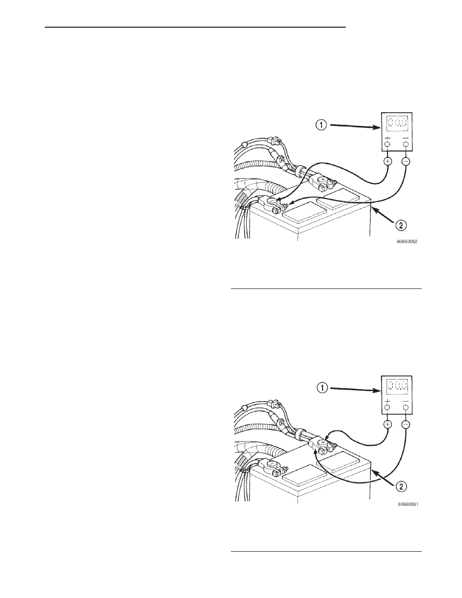
(2) Connect the positive lead of the voltmeter to

the battery positive terminal post. Connect the nega-
tive lead of the voltmeter to the battery positive cable
terminal clamp (Fig. 14). Rotate and hold the ignition
switch in the Start position. Observe the voltmeter. If
voltage is detected, correct the poor connection
between the battery positive cable terminal clamp
and the battery positive terminal post.

Fig. 13 Test Battery Negative Connection

Resistance - Typical

1 – VOLTMETER
2 – BATTERY

Fig. 14 Test Battery Positive Connection Resistance

- Typical

1 – VOLTMETER
2 – BATTERY

DN

BATTERY

8A - 15

DIAGNOSIS AND TESTING (Continued)

(3) Connect the voltmeter to measure between the

battery positive cable terminal clamp and the starter
solenoid B(+) terminal stud (Fig. 15). Rotate and hold
the ignition switch in the Start position. Observe the
voltmeter. If the reading is above 0.2 volt, clean and
tighten the battery positive cable eyelet terminal con-
nection at the starter solenoid B(+) terminal stud.
Repeat the test. If the reading is still above 0.2 volt,
replace the faulty battery positive cable.

(4) Connect the voltmeter to measure between the

battery negative cable terminal clamp and a good
clean ground on the engine block (Fig. 16). Rotate
and hold the ignition switch in the Start position.
Observe the voltmeter. If the reading is above 0.2
volt, clean and tighten the battery negative cable
eyelet terminal connection to the engine block.
Repeat the test. If the reading is still above 0.2 volt,
replace the faulty battery negative cable.

SERVICE PROCEDURES

BATTERY CHARGING

Battery charging is the means by which the bat-

tery can be restored to its full voltage potential. A
battery is fully-charged when:

• All of the battery cells are gassing freely during

battery charging.

• A green color is visible in the sight glass of the

battery built-in test indicator.

• Three hydrometer tests, taken at one-hour inter-

vals, indicate no increase in the temperature-cor-
rected specific gravity of the battery electrolyte.

• Open-circuit voltage of the battery is 12.4 volts

or above.

WARNING:

IF THE BATTERY SHOWS SIGNS OF FREEZ-

ING, LEAKING, LOOSE POSTS, OR LOW ELECTRO-
LYTE LEVEL, DO NOT TEST, ASSIST-BOOST, OR
CHARGE. THE BATTERY MAY ARC INTERNALLY
AND EXPLODE. PERSONAL INJURY AND/OR VEHI-
CLE DAMAGE MAY RESULT.

EXPLOSIVE HYDROGEN GAS FORMS IN AND

AROUND THE BATTERY. DO NOT SMOKE, USE
FLAME, OR CREATE SPARKS NEAR THE BATTERY.
PERSONAL INJURY AND/OR VEHICLE DAMAGE
MAY RESULT.

THE BATTERY CONTAINS SULFURIC ACID,

WHICH IS POISONOUS AND CAUSTIC. AVOID CON-
TACT WITH THE SKIN, EYES, OR CLOTHING. IN
THE EVENT OF CONTACT, FLUSH WITH WATER
AND CALL A PHYSICIAN IMMEDIATELY. KEEP OUT
OF THE REACH OF CHILDREN.

IF THE BATTERY IS EQUIPPED WITH REMOV-

ABLE CELL CAPS, BE CERTAIN THAT EACH OF
THE CELL CAPS IS IN PLACE AND TIGHT BEFORE
THE BATTERY IS RETURNED TO SERVICE. PER-
SONAL INJURY AND/OR VEHICLE DAMAGE MAY
RESULT FROM LOOSE OR MISSING CELL CAPS.

Fig. 15 Test Battery Positive Cable Resistance -

Typical

1 – BATTERY
2 – VOLTMETER
3 – STARTER MOTOR

Fig. 16 Test Ground Circuit Resistance - Typical

1 – VOLTMETER
2 – BATTERY
3 – ENGINE GROUND

8A - 16

BATTERY

DN

DIAGNOSIS AND TESTING (Continued)

CAUTION:

Always disconnect and isolate the battery neg-

ative cable before charging a battery. Do not exceed
sixteen volts while charging a battery. Damage to
the vehicle electrical system components may
result.

Battery electrolyte will bubble inside the bat-

tery case during normal battery charging. Electro-
lyte boiling or being discharged from the battery
vents indicates a battery overcharging condition.
Immediately reduce the charging rate or turn off the
charger to evaluate the battery condition. Damage
to the battery may result from overcharging.

The battery should not be hot to the touch. If

the battery feels hot to the touch, turn off the
charger and let the battery cool before continuing
the charging operation. Damage to the battery may
result.

Some battery chargers are equipped with polarity-

sensing circuitry. This circuitry protects the battery
charger and the battery from being damaged if they
are improperly connected. If the battery state-of-
charge is too low for the polarity-sensing circuitry to
detect, the battery charger will not operate. This
makes it appear that the battery will not accept
charging current. See the instructions provided by
the manufacturer of the battery charger for details
on how to bypass the polarity-sensing circuitry.

After the battery has been charged to 12.4 volts or

greater, perform a load test to determine the battery
cranking capacity. Refer to Battery in the index of
this service manual for the location of the battery
diagnosis and testing procedures for more informa-
tion on the proper battery load testing procedures. If
the battery will endure a load test, return the bat-
tery to service. If the battery will not endure a load
test, it is faulty and must be replaced.

Clean and inspect the battery hold downs, tray,

terminals, posts, and top before completing battery
service. Refer to Battery in the index of this service
manual for the location of the proper battery clean-
ing and inspection procedures.

CHARGING A COMPLETELY DISCHARGED
BATTERY

The following procedure should be used to recharge

a completely discharged battery. Unless this proce-
dure is properly followed, a good battery may be
needlessly replaced.

(1) Measure the voltage at the battery posts with a

voltmeter, accurate to 1/10 (0.10) volt (Fig. 17). If the
reading is below ten volts, the battery charging cur-
rent will be low. It could take some time before the
battery accepts a current greater than a few milliam-

peres. Such low current may not be detectable on the
ammeters built into many battery chargers.

(2) Disconnect and isolate the battery negative

cable. Connect the battery charger leads. Some bat-
tery chargers are equipped with polarity-sensing cir-
cuitry. This circuitry protects the battery charger and
the battery from being damaged if they are improp-
erly connected. If the battery state-of-charge is too
low for the polarity-sensing circuitry to detect, the
battery charger will not operate. This makes it
appear that the battery will not accept charging cur-
rent. See the instructions provided by the manufac-
turer of the battery charger for details on how to
bypass the polarity-sensing circuitry.

(3) Battery chargers vary in the amount of voltage

and current they provide. The amount of time
required for a battery to accept measurable charging
current at various voltages is shown in the Charge
Rate chart. If the charging current is still not mea-
surable at the end of the charging time, the battery
is faulty and must be replaced. If the charging cur-
rent is measurable during the charging time, the bat-
tery may be good and the charging should be
completed in the normal manner.

CHARGING TIME REQUIRED

The time required to charge a battery will vary,

depending upon the following factors:

• Battery Capacity

A completely discharged heavy-duty battery requires
twice the charging time of a small capacity battery.

Fig. 17 Voltmeter Accurate to 1/10 Volt Connected -

Typical

Charge Rate

Voltage

Hours

16.0 volts maximum

up to 4 hours

14.0 to 15.9 volts

up to 8 hours

13.9 volts or less

up to 16 hours

DN

BATTERY

8A - 17

SERVICE PROCEDURES (Continued)

• Temperature

A longer time will be needed to charge a battery at
-18° C (0° F) than at 27° C (80° F). When a fast bat-
tery charger is connected to a cold battery, the cur-
rent accepted by the battery will be very low at first.
As the battery warms, it will accept a higher charg-
ing current rate (amperage).

• Charger Capacity

A battery charger that supplies only five amperes
will require a longer charging time. A battery charger
that supplies twenty amperes or more will require a
shorter charging time.

• State-Of-Charge

A completely discharged battery requires more charg-
ing time than a partially discharged battery. Electro-
lyte is nearly pure water in a completely discharged
battery. At first, the charging current (amperage) will
be low. As the battery charges, the specific gravity of
the electrolyte will gradually rise.

WARNING: NEVER

EXCEED

TWENTY AMPERES

WHEN CHARGING A COLD (-1° C or 30° F) BAT-
TERY. THE BATTERY MAY ARC INTERNALLY AND
EXPLODE. PERSONAL INJURY AND/OR VEHICLE
DAMAGE MAY RESULT.

REMOVAL AND INSTALLATION

BATTERY HOLD DOWNS

REMOVAL

(1) Turn the ignition switch to the Off position. Be

certain that all electrical accessories are turned off.

(2) Loosen the battery negative cable terminal

clamp pinch-bolt hex nut.

(3) Disconnect the battery negative cable terminal

clamp from the battery negative terminal post. If

necessary, use a battery terminal puller to remove
the terminal clamp from the battery post.

(4) Disconnect the battery positive cable terminal

clamp from the battery positive terminal post. If nec-
essary, use a battery terminal puller to remove the
terminal clamp from the battery post.

(5) Remove the two hold down bolts that secure

the hold down strap/battery thermoguard unit to the
U-nuts in the battery tray (Fig. 18).

(6) Remove the hold down strap/battery thermo-

guard unit from the top of the battery case.

INSTALLATION

(1) Clean and inspect the battery hold down hard-

ware. Refer to Battery in the index of this service
manual for the location of the proper battery hold
down hardware cleaning and inspection procedures.

(2) Install the hold down strap/battery thermo-

guard unit over the top of the battery case.

Battery Charging Timetable

Charging

Amperage

5

Amperes

10

Amperes

20

Amperes

Open

Circuit

Voltage

Hours Charging at 21° C (70° F)

12.25 to

12.49

6 hours

3 hours

1.5 hours

12.00 to

12.24

10 hours

5 hours

2.5 hours

10.00 to

11.99

14 hours

7 hours

3.5 hours

*Below

10.00

18 hours

9 hours

4.5 hours

*Refer to Charging A Completely Discharged Battery

Fig. 18 Battery Hold Downs Remove/Install

1 – CLIPS
2 – BOLT
3 – TRAY
4 – BATTERY
5 – HOLD DOWN STRAP AND THERMOGUARD
6 – POSITIVE CABLE
7 – NEGATIVE CABLE

8A - 18

BATTERY

DN

SERVICE PROCEDURES (Continued)


Content   ..  263  264  265  266   ..