Dodge Durango (DN). Manual - part 258
(2) Partially drain cooling system. Refer to COOL-
ING SYSTEM—DRAINING and FILLING in this
Section.
Do not waste reusable coolant. If solution is clean,
drain coolant into a clean container for reuse.
(3) Remove upper radiator hose clamp (Fig. 38)
and hose at radiator.
(4) Unplug wiring harness from A/C compressor.
(5) Remove air cleaner assembly.
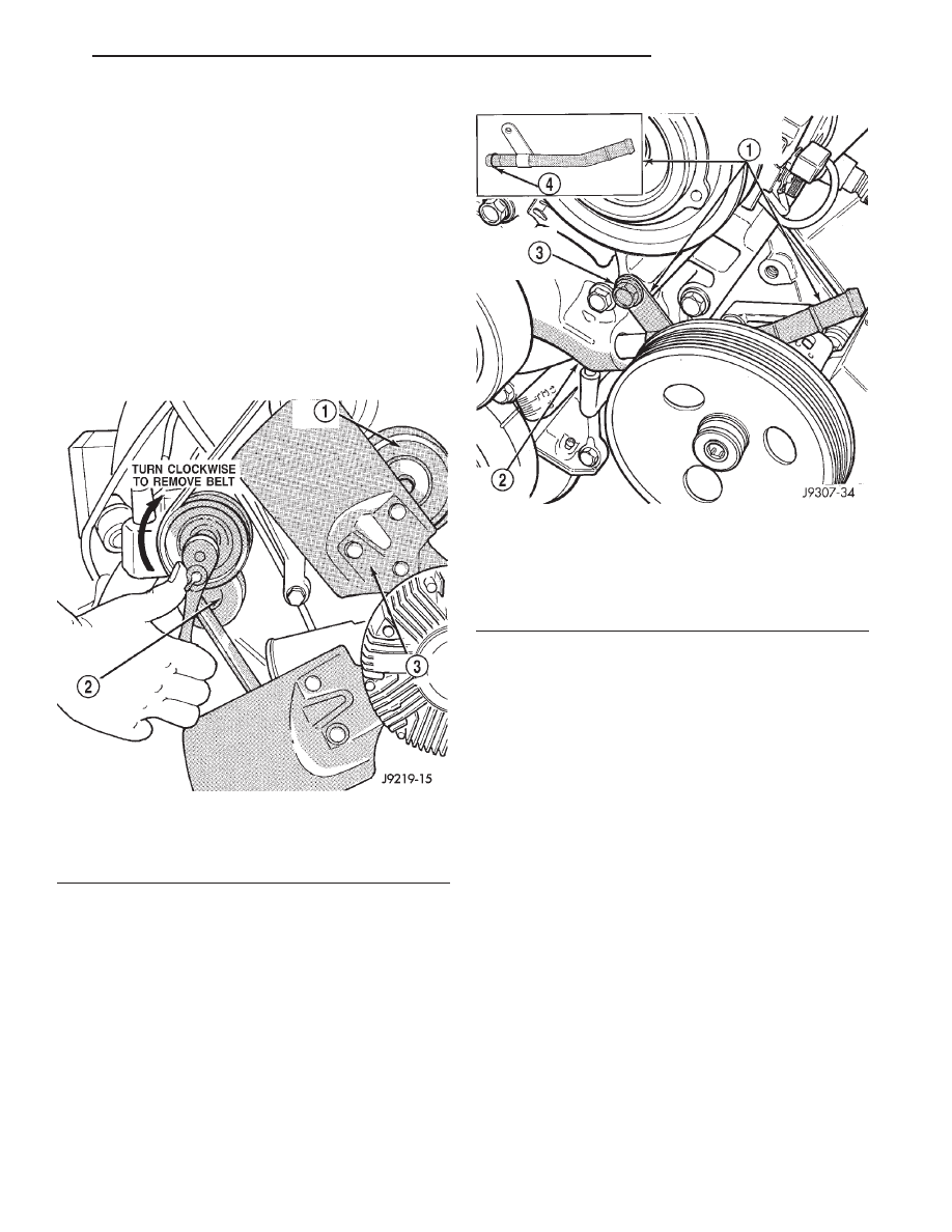
(6) Remove accessory drive belt as follows: The
drive belt is equipped with a spring loaded automatic
tensioner (Fig. 41). Relax tension from belt by rotat-
ing tensioner clockwise (as viewed from front) (Fig.
41). When all belt tension has been relaxed, remove
accessory drive belt.
(7) The drive belt idler pulley must be removed to
gain access to one of A/C compressor/generator
bracket mounting bolts. Remove idler pulley bolt and
remove idler pulley (Fig. 40).
(8) Remove oil dipstick tube mounting bolt at side
of A/C-generator mounting bracket.
(9) Disconnect throttle body control cables. Refer
to ACCELERATOR PEDAL and THROTTLE CABLE
in FUEL SYSTEM for procedure.
(10) Remove heater hose clamp and heater hose
from heater hose coolant return tube.
(11) Remove
heater
hose
coolant
return
tube
mounting bolt (Fig. 42) and remove tube from engine.
Discard the old tube O-ring.
(12) Remove
bracket-to-intake
manifold
bolts
(number 1 and 2— (Fig. 40).
(13) Remove six bracket bolts (number 3— (Fig.
40).
(14) Lift and position generator and A/C compres-
sor (along with their common mounting bracket) to
gain access to bypass hose. A block of wood may be
used to hold assembly in position.
(15) Loosen and position both hose clamps to cen-
ter of bypass hose. Remove hose from vehicle.
INSTALLATION
(1) Position bypass hose clamps to center of hose.
(2) Install bypass hose to engine.
(3) Secure both hose clamps (Fig. 38).
(4) Install generator-A/C mounting bracket assem-
bly to engine. Tighten bolts (number 1 and 2— (Fig.
40) to 54 N·m (40 ft. lbs.) torque. Tighten bolts (num-
ber 3— (Fig. 40) to 40 N·m (30 ft. lbs.) torque.
(5) Install a new O-ring to the heater hose coolant
return tube (Fig. 42). Coat the new O-ring with anti-
freeze before installation.
(6) Install coolant return tube and its mounting
bolt to engine (Fig. 42).
(7) Connect throttle body control cables.
(8) Install oil dipstick mounting bolt.
Fig. 41 Automatic Belt Tensioner Assembly
1 – IDLER PULLEY
2 – TENSIONER
3 – FAN BLADE
Fig. 42 Coolant Return Tube—5.2L/5.9L Engines—
Typical
1 – COOLANT RETURN TUBE
2 – WATER PUMP
3 – TUBE MOUNTING BOLT
4 – O-RING
DN
COOLING SYSTEM
7 - 31
REMOVAL AND INSTALLATION (Continued)