Dodge Durango (DN). Manual - part 236
PINION DEPTH MEASUREMENT AND ADJUSTMENT
Measurements are taken with pinion bearing cups
and pinion bearings installed in the axle housing.
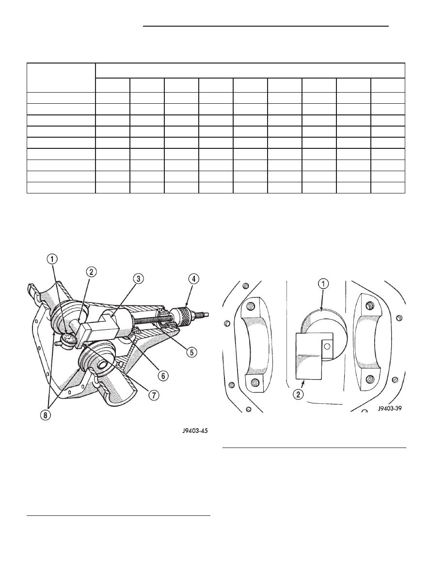
Take measurements with Pinion Gauge Set and Dial
Indicator C-3339 (Fig. 75).
(1) Assemble Pinion Height Block 6739, Pinion
Block 8542, and rear pinion bearing onto Screw 6741
(Fig. 75).
(2) Insert assembled height gauge components,
rear bearing, and screw into axle housing through
pinion bearing cups (Fig. 76).
(3) Install front pinion bearing and Cone-Nut 6740
hand tight (Fig. 75).
(4) Place Arbor Disc 8541 on Arbor D-115-3 in posi-
tion in axle housing side bearing cradles (Fig. 77).
Install differential bearing caps on Arbor Discs and
tighten cap bolts to 41 N·m (30 ft. lbs.).
NOTE: Arbor Discs 8541 has different step diame-
ters to fit other axles. Choose proper step for axle
being serviced.
PINION GEAR DEPTH VARIANCE
Original Pinion
Gear Depth
Variance
Replacement Pinion Gear Depth Variance
−4
−3
−2
−1
0
+1
+2
+3
+4
+4
+0.008
+0.007
+0.006
+0.005
+0.004
+0.003
+0.002
+0.001
0
+3
+0.007
+0.006
+0.005
+0.004
+0.003
+0.002
+0.001
0
−0.001
+2
+0.006
+0.005
+0.004
+0.003
+0.002
+0.001
0
−0.001
−0.002
+1
+0.005
+0.004
+0.003
+0.002
+0.001
0
−0.001
−0.002
−0.003
0
+0.004
+0.003
+0.002
+0.001
0
−0.001
−0.002
−0.003
−0.004
−1
+0.003
+0.002
+0.001
0
−0.001
−0.002
−0.003
−0.004
−0.005
−2
+0.002
+0.001
0
−0.001
−0.002
−0.003
−0.004
−0.005
−0.006
−3
+0.001
0
−0.001
−0.002
−0.003
−0.004
−0.005
−0.006
−0.007
−4
0
−0.001
−0.002
−0.003
−0.004
−0.005
−0.006
−0.007
−0.008
Fig. 75 Pinion Gear Depth Gauge Tools
1 – DIAL INDICATOR
2 – ARBOR
3 – PINION HEIGHT BLOCK
4 – CONE
5 – SCREW
6 – PINION BLOCK
7 – SCOOTER BLOCK
8 – ARBOR DISC
Fig. 76 Pinion Height Block
1 – PINION BLOCK
2 – PINION HEIGHT BLOCK
3 - 94
8 1/4 AND 9 1/4 AXLE
DN
ADJUSTMENTS (Continued)