Dodge Durango (DN). Manual - part 201
outlet and secure the connection with a screw.
Tighten the mounting screw to 13.5 N·m (120 in.
lbs.). Connect the suction line from the suction dis-
charge assembly to the suction jumper tube.
(6) Reinstall the nut that secures the ground strap
to the inboard side of the rear liquid line block fit-
ting. Tighten the mounting screw to 6.8 N·m (60 in.
lbs.).
(7) Reinstall the engine air filter housing. Refer to
Group 14 - Fuel System for the procedures.
(8) Connect the battery negative cable.
(9) Evacuate the refrigerant system. See Refriger-
ant System Evacuate in the Service Procedures sec-
tion of this group.
(10) Charge the refrigerant system. See Refriger-
ant System Charge in the Service Procedures section
of this group.
LOW PRESSURE CUT-OFF SWITCH
REMOVAL
(1) Disconnect and isolate the battery negative
cable.
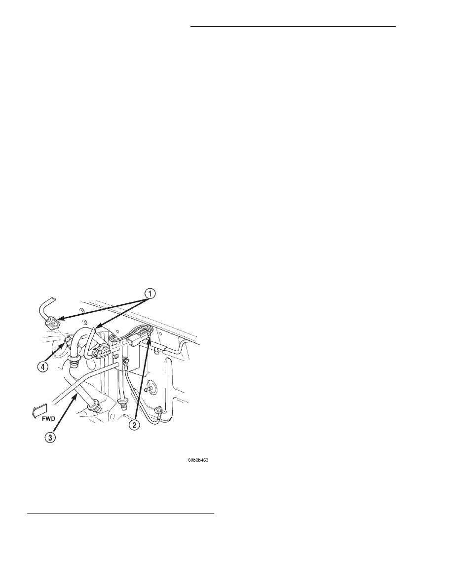
(2) Unplug the wire harness connector from the
low pressure cut-off switch on the suction line jumper
near the expansion valve (Fig. 75).
(3) Unscrew the low pressure cut-off switch from
the fitting on the suction line jumper.
(4) Remove the O-ring seal from the suction line
jumper fitting and discard.
INSTALLATION
(1) Lubricate a new O-ring seal with clean refrig-
erant oil and install it on the suction line jumper fit-
ting. Use only the specified O-rings as they are made
of a special material for the R-134a system. Use only
refrigerant oil of the type recommended for the com-
pressor in the vehicle.
(2) Install and tighten the low pressure cut-off
switch on the suction line jumper fitting. The switch
should be hand-tightened onto the fitting.
(3) Plug the wire harness connector into the low
pressure cut-off switch.
(4) Connect the battery negative cable.
MODE DOOR VACUUM ACTUATOR
WARNING: ON VEHICLES EQUIPPED WITH AIR-
BAGS,
REFER
TO
GROUP
8M
-
PASSIVE
RESTRAINT SYSTEMS BEFORE ATTEMPTING ANY
STEERING
WHEEL,
STEERING
COLUMN,
OR
INSTRUMENT PANEL COMPONENT DIAGNOSIS OR
SERVICE. FAILURE TO TAKE THE PROPER PRE-
CAUTIONS COULD RESULT IN ACCIDENTAL AIR-
BAG DEPLOYMENT AND POSSIBLE PERSONAL
INJURY.
FLOOR-DEFROST DOOR ACTUATOR
(1) Disconnect and isolate the battery negative
cable.
(2) Remove the instrument panel assembly from
the vehicle. Refer to Instrument Panel Assembly in
the Removal and Installation section of Group 8E -
Instrument Panel Systems for the procedures.
(3) Unplug the two vacuum harness connectors
from the floor-defrost door actuator (Fig. 76).
(4) Remove the push nut retainer that secures the
floor-defrost door actuator link to the floor-defrost
door crank arm.
(5) Remove the two screws that secure the floor-
defrost door actuator to the heater-A/C housing.
(6) Disengage the floor-defrost door actuator link
from the floor-defrost door crank arm and remove the
actuator from the heater-A/C housing.
(7) Reverse the removal procedures to install.
Tighten the floor-defrost door actuator mounting
screws to 2.2 N·m (20 in. lbs.).
PANEL-DEFROST DOOR ACTUATOR
(1) Disconnect and isolate the battery negative
cable.
(2) Remove the instrument panel assembly from
the vehicle. Refer to Instrument Panel Assembly in
Fig. 75 Low Pressure Cut-Off Switch Remove/Install
1 – WIRE HARNESS CONNECTORS
2 – TO ELECTRONIC CYCLING CLUTCH SWITCH
3 – SUCTION LINE JUMPER
4 – LOW PRESSURE CUT-OFF SWITCH
24 - 62
HEATING AND AIR CONDITIONING
DN
REMOVAL AND INSTALLATION (Continued)