Dodge Durango (DN). Manual - part 162


  Index      Dodge     Dodge Durango (DN) - service repair manual 2000 year


Search            


Content   ..  160  161  162  163   ..


Dodge Durango (DN). Manual - part 162


(10) Install right headlamp module.
(11) Install wheelhouse liner.
(12) Install wheel opening molding.
(13) Install right front wheel.
(14) Remove the support and lower the vehicle.
(15) Connect battery negative cable.
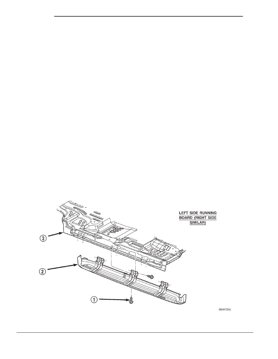
RUNNING BOARD

REMOVAL

The running boards can be removed and installed

on the vehicle as an assembly.

(1) Remove the fasteners from the wheel opening

molding (Fig. 17).

(2) Remove the fasteners retaining the running

board brackets to the body (Fig. 16).

(3) Separate the running boards from the vehicle.

INSTALLATION

(1) Position the running boards on the vehicle.
(2) Install the bolts retaining the running board

brackets to the body.

(3) Install the fasteners in the wheel opening

molding.

EXTERIOR NAMEPLATES

REMOVAL

NOTE: Exterior nameplates are attached to body
panels with adhesive tape.

(1) Apply a length of masking tape on the body,

parallel to the top edge of the nameplate to use as a
guide, if necessary.

(2) If temperature is below 21°C (70°F) warm

emblem with a heat lamp or gun. Do not exceed 52°C
(120°F) when heating emblem.

(3) Insert a plastic trim stick or a hard wood

wedge behind the emblem to separate the adhesive
backing from the body.

(4) Clean adhesive residue from body with MOPAR

Super Clean solvent or equivalent.

INSTALLATION

(1) Remove carrier from adhesive tape on back of

emblem.

(2) Position emblem properly on body (Fig. 18).
(3) Press emblem firmly to body with palm of

hand.

(4) If temperature is below 21°C (70°F) warm

emblem with a heat lamp or gun to assure adhesion.
Do not exceed 52°C (120°F) when heating emblem.

Fig. 16 Running Board Left Side

1 – SCREW
2 – RUNNING BOARD

3 – LEFT UNDERBODY RAIL

23 - 28

BODY

DN

REMOVAL AND INSTALLATION (Continued)

Fig. 17 Running Boards

1 – SCREW
2 – BOLT

Fig. 18 Hood/Fender Nameplates

1 – HOOD NAMEPLATE
2 – ENGINE NAMEPLATE

DN

BODY

23 - 29

REMOVAL AND INSTALLATION (Continued)

DECALS

REMOVAL

(1) Warm the panel to approximately 38°C (100°F)

using a suitable heat lamp or heat gun.

(2) Peel decal from body panel (Fig. 19) and (Fig.

20) using an even pressure pull.

(3) Remove adhesive residue from body panel

using a suitable adhesive removing solvent.

INSTALLATION

The painted surface of the body panel to be covered

by a decal must be smooth and completely cured
before decal can be applied. Ripples and feather edg-
ing will read through if surface is not properly pre-
pared. Clean all residue from surface.

(1) Peel paper backing away from decal exposing

adhesive back of decal.

(2) Apply soap solution liberally to adhesive back

of decal.

(3) Apply soap solution liberally to body panel sur-

face.

(4) Place decal into position on body panel. Smooth

out wrinkles by pulling lightly on edges of decal until
it lays flat on painted surface.

(5) Push air pockets from under decal to the

perimeter of the panel from the center of the decal
out.

(6) Squeegee soap solution and air bubbles from

behind decal from the center of the panel out using a
body putty applicator squeegee.

(7) Apply heat to decal to evaporate residual mois-

ture from edges of decal.

(8) Small air or water bubbles under decal can be

pierced with a pin and smoothed out.

SIDE VIEW MIRROR

REMOVAL

(1) Remove door trim panel.
(2) Remove mirror flag seal (Fig. 21).
(3) Disengage power mirror wire connector from

door harness, if equipped (Fig. 22).

(4) Remove nuts attaching side view mirror to door

frame.

(5) Separate harness grommet form door frame, if

equipped.

(6) Separate side view mirror from vehicle.

INSTALLATION

(1) Position side view mirror on vehicle.
(2) Install harness grommet in door frame, if

equipped.

(3) Install nuts attaching side view mirror to door

frame. Tighten nuts to 7 N·m (65 in. lbs.) torque.

Fig. 19 Door Decals

1 – “DURANGO” DECAL
2 – FRONT DOOR
3 – “SLT” DECAL

Fig. 20 Liftgate Decals

1 – LIFTGATE

Fig. 21 Mirror Flag Door Seal

1 – STUFFERS
2 – MIRROR FLAG SEAL

23 - 30

BODY

DN

REMOVAL AND INSTALLATION (Continued)

(4) Engage power mirror wire connector from door

harness, if equipped.

(5) Install mirror flag seal.
(6) Install door trim panel.

FRONT DOOR TRIM PANEL

REMOVAL

(1) Release door latch and open door.
(2) Roll window down.
(3) Remove window crank (Fig. 23), if equipped.
(4) Remove screws attaching trim panel to door

(Fig. 24) and (Fig. 25).

CAUTION: Do not forcibly pull trim panel from
door, damage to trim panel may occur.

(5) Simultaneously lift upward and outward to

release retainer steps from inner door panel (Fig. 26).

(6) Disengage inside handle linkage rod from

inside handle.

(7) Disconnect speaker harness wire connector

(Fig. 27).

(8) Disengage power mirror wire connector, if

equipped (driver’s side only) (Fig. 27).

(9) Disengage clips attaching power window/lock

switch panel to door trim panel. Disengage wire con-
nector from switch panel, if equipped (Fig. 28).

(10) Separate door trim panel from vehicle.

INSTALLATION

(1) Position trim panel at door.
(2) Engage wire connector for window/lock switch

panel, if equipped.

(3) Engage

power

mirror

wire

connector,

if

equipped.

(4) Connect speaker harness wire connector.
(5) Engage inside handle linkage rod to inside

handle.

(6) Align trim panel retainer steps with inner door

panel and slide trim panel into place.

(7) Install screws attaching trim panel to door.
(8) Install window crank, if equipped.

FRONT DOOR WATERDAM

REMOVAL

(1) Remove the trim panel from the door.
(2) Carefully separate the waterdam from the door

inner panel at the areas with adhesive (Fig. 29).
Remove the waterdam from the door inner panel.

Fig. 22 Side View Mirror Connectors

1 – ELECTRIC FOLD AWAY SIDEVIEW MIRROR
2 – DOOR
3 – ELECTRIC SIDEVIEW MIRROR

Fig. 23 Window Crank—Typical

1 – WINDOW CRANK REMOVAL TOOL
2 – WINDOW CRANK

Fig. 24 Door Trim Panel

1 – TRIM PANEL

DN

BODY

23 - 31

REMOVAL AND INSTALLATION (Continued)


Content   ..  160  161  162  163   ..