Dodge Durango (DN). Manual - part 157


  Index      Dodge     Dodge Durango (DN) - service repair manual 2000 year


Search            


Content   ..  155  156  157  158   ..


Dodge Durango (DN). Manual - part 157


QUARTER WINDOW GLASS

REMOVAL

(1) Remove quarter panel trim.
(2) Carefully pull down headliner to access upper

nuts attaching quarter window glass to pinchweld
and remove nuts.

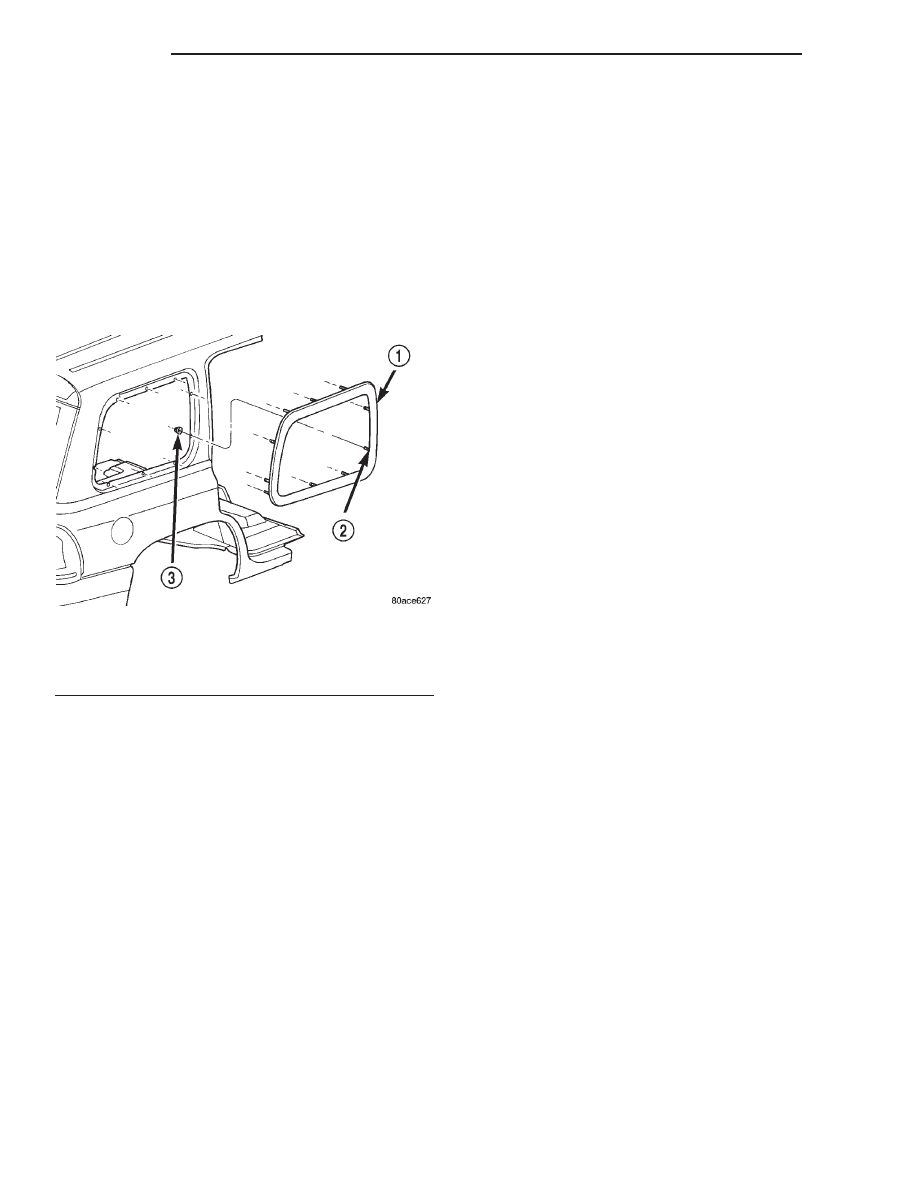
(3) Remove nuts attaching quarter window glass to

pinchweld (Fig. 7).

(4) Using razor knife, cut butyl sealer between the

mounting studs attaching glass to pinchweld.

(5) Push glass from opening.

INSTALLATION

The pinchweld should be cleaned of all old butyl sealer.
(1) Apply 6 mm (0.25 in.) of butyl tape around

perimeter of glass assembly encapsulation track.

Ensure the butyl tape is wrapped around the mount-
ing studs.

(2) Place glass into opening and insert mounting

studs through holes in pinchweld.

(3) Install nuts attaching quarter window glass to

pinchweld. Tighten nuts to 4.5 N·m (40 in. lbs.)
torque.

(4) Install interior trim.

LIFTGATE BACKLITE

REMOVAL

Refer to the Windshield paragraph of this section

for all warnings and cautions.

(1) Remove liftgate upper trim panel.
(2) Remove CHMSL.
(3) Remove rear window wiper arm, if equipped.
(4) Remove side moldings.
(5) Cut urethane bonding from around liftgate

backlite using a suitable sharp cold knife. A pneu-
matic cutting device can be used if available.

(6) Separate backlite from vehicle.

INSTALLATION

CAUTION: Open a window before installing back-
lite. This will avoid pressurizing the passenger com-
partment. If a door is slammed before urethane is
cured, water leaks can result.

The window opening fence should be cleaned of old

urethane bonding material.

(1) Clean inside of backlite with Mopar Glass

Cleaner or equivalent and lint-free cloth.

(2) Apply PVC (vinyl) primer 25 mm (1 in.) wide

around edge of backlite. Wipe with clean/dry lint-free
cloth.

(3) Apply fence primer around edge of fence. Allow

at least eighteen minutes drying time.

(4) Install new upper and lower seals on liftgate

backlite (Fig. 8).

Fig. 7 Quarter Window Glass

1 – QUARTER GLASS
2 – STUD
3 – NUT

23 - 8

BODY

DN

REMOVAL AND INSTALLATION (Continued)

(5) Apply a 12 mm (0.4 in.) bead of urethane

around window opening fence.
Position backlite into window opening (Fig. 9).

Fig. 9 Liftgate Backlite

1 – BACKLITE
2 – LIFTGATE

Fig. 8 Liftgate Backlite Seals

1 – UPPER SEAL
2 – LIFTGATE BACKLITE
3 – LOWER SEAL

DN

BODY

23 - 9

REMOVAL AND INSTALLATION (Continued)

SEATS

TABLE OF CONTENTS

page

page

DESCRIPTION AND OPERATION

SEAT SYSTEMS. . . . . . . . . . . . . . . . . . . . . . . . . . 10

REMOVAL AND INSTALLATION

SIDE SHIELD . . . . . . . . . . . . . . . . . . . . . . . . . . . . 10
TOWEL BAR . . . . . . . . . . . . . . . . . . . . . . . . . . . . 10
BUCKET SEAT TRACK. . . . . . . . . . . . . . . . . . . . . 10
BUCKET SEAT BACK . . . . . . . . . . . . . . . . . . . . . . 11
BUCKET SEAT BACK COVER/CUSHION . . . . . . . 11
BUCKET SEAT CUSHION/COVER . . . . . . . . . . . . 11
BUCKET SEAT RECLINER . . . . . . . . . . . . . . . . . . 12
CENTER SEAT/CONSOLE . . . . . . . . . . . . . . . . . . 12
CENTER ARMREST/CONSOLE INERTIA

LATCH COVER . . . . . . . . . . . . . . . . . . . . . . . . . 12

CENTER SEAT CUSHION/COVER . . . . . . . . . . . . 13

2ND ROW SEAT BACK . . . . . . . . . . . . . . . . . . . . 13
2ND ROW SEAT BACK COVER . . . . . . . . . . . . . . 14
2ND ROW SEAT CUSHION COVER . . . . . . . . . . . 14
2ND ROW SEAT CUSHION . . . . . . . . . . . . . . . . . 14
2ND ROW SEAT LATCHES . . . . . . . . . . . . . . . . . 14
2ND ROW CENTER SEAT CUSHION COVER . . . 15
2ND ROW CENTER SEAT CUSHION . . . . . . . . . . 15
2ND ROW CENTER SEAT BACK . . . . . . . . . . . . . 16
2ND ROW CENTER SEAT BACK COVER. . . . . . . 16
3RD ROW SEAT CUSHION COVER . . . . . . . . . . . 16
3RD ROW SEAT CUSHION FRAME . . . . . . . . . . . 16
HEAD RESTRAINT SLEEVE. . . . . . . . . . . . . . . . . 17
3RD ROW SEAT BACK . . . . . . . . . . . . . . . . . . . . 17
3RD ROW SEAT BACK COVER . . . . . . . . . . . . . . 17

DESCRIPTION AND OPERATION

SEAT SYSTEMS

DESCRIPTION

Seat modules are made up of a seat frame, seat

cushion, seat back cushion, a covering material, and
the electrical components used for power operation, if
equipped. Some seat systems also contain seat belt
components and supplemental restraint systems.

OPERATION

Seat assemblies transport the occupants in comfort

and safety. Seat assemblies also help position occu-
pants correctly in the event of airbag deployment.
Seat cushions, coverings, and electrical components
are serviceable. Refer to the appropriate group in
this manual.

REMOVAL AND INSTALLATION

SIDE SHIELD

REMOVAL

(1) Remove screw attaching recliner handle to

seat.

(2) Remove recliner handle.
(3) Remove screws attaching side shield to seat.
(4) Disengage power seat harness connector, if

equipped.

(5) Separate side shield from seat.

INSTALLATION

(1) Engage

power

seat

harness

connector,

if

equipped.

(2) Position side shield on seat.
(3) Install screws attaching side shield to seat.
(4) Install recliner handle.

TOWEL BAR

REMOVAL

The towel bar is attached to the seat cushion frame

with unthreaded stud retainers (Fig. 1).

(1) From

the

underside

of

the

seat,

remove

unthreaded stud retainers.

(2) Squeeze ends of towel bar inward to release

from pivot studs.

(3) Separate towel bar from cushion frame.

INSTALLATION

(1) position towel bar on pivot studs.

NOTE: To

ensure

positive

retention,

use

new

unthreaded stud retainers to secure towel bar onto
pivot studs.

(2) Install unthreaded stud retainers.

BUCKET SEAT TRACK

REMOVAL

(1) Remove seat.
(2) Adjust the seat track to gain access to the torx

bolts attaching the seat track to the cushion frame.

(3) Remove the torx bolts.

23 - 10

BODY

DN

(4) Remove the unthreaded stud retainers from

the towel bar.

(5) Separate the seat track from the frame.

INSTALLATION

(1) Position the seat track on the frame.
(2) Install the unthreaded stud retainers on the

towel bar.

(3) Install the torx bolts attaching the seat track

to the cushion frame. Tighten the bolts in sequence
(Fig. 2) to 24 N·m (17 ft. lbs.) torque.

(4) Install seat.

BUCKET SEAT BACK

The bucket seat back frame, seat cushion frame

and recliner mechanism is serviced as a complete
assembly. Refer to the Bucket Seat Cushion/Cover
and Bucket Seat Back Pad/Cover for service proce-
dures.

BUCKET SEAT BACK COVER/CUSHION

NOTE: CLOTH TRIM IS BONDED TO THE CUSHION
FOAM.

REMOVAL

(1) Position seat in full forward position.
(2) Disengage J-strap at base of seat back.
(3) Using a trim stick, carefully pry off lumbar

handle (driver’s side only).

(4) Disengage wire hanger securing back pad to

frame.

(5) Separate cover/cushion from seat back frame.

INSTALLATION

(1) Position cover/cushion on seat back frame.
(2) Engage wire hanger.
(3) Engage J-straps at base of seat back.
(4) Position lumbar handle on lumbar adjuster and

press into place.

(5) Return seat to normal position.

BUCKET SEAT CUSHION/COVER

NOTE: CLOTH TRIM IS BONDED TO THE CUSHION
FOAM

REMOVAL

(1) Remove the anchor bolt attaching the seat belt

to the seat track (Fig. 3).

(2) Remove seat.
(3) Remove the screw attaching the recliner handle

to the recliner mechanism.

(4) Remove seat side shield and disconnect wire

harness.

(5) Disengage the rearward J-straps.
(6) Disengage both side J-straps.
(7) Disengage the front J-strap.
(8) Disengage hook and loop fasteners.
(9) Separate the cushion/cover from the frame.

INSTALLATION

(1) Install anti-squeak sheet.
(2) Position the cushion/cover on the frame.
(3) Engage the front J-strap.
(4) Engage the side J-straps.
(5) Engage the rearward corner J-straps.
(6) Engage hook and loop fasteners.
(7) Engage the rear J-strap.
(8) Install the recliner handle.
(9) Install seat. Tighten the front seat track bolts

to 22–34 N·m (16–25 ft. lbs.). Tighten the rear seat
track bolts to 89–140 N·m (66–103 ft lbs.).

Fig. 1 Towel Bar

1 – TOWEL BAR
2 – CUSHION FRAME
3 – PIVOT STUD
4 – UNTHREADED STUD RETAINERS

Fig. 2 Bucket Seat Track

DN

BODY

23 - 11

REMOVAL AND INSTALLATION (Continued)


Content   ..  155  156  157  158   ..