Dodge Durango (DN). Manual - part 109


  Index      Dodge     Dodge Durango (DN) - service repair manual 2000 year


Search            


Content   ..  107  108  109  110   ..


Dodge Durango (DN). Manual - part 109


(3) Position Guide Ring 8114-1 on outer edge of

overdrive piston retainer.

(4) Position Seal Guide 8114-3 on inner edge of

overdrive piston retainer.

(5) Install overdrive piston in overdrive piston

retainer by:

(a) Aligning locating lugs on overdrive piston to

the two mating holes in retainer.

(b) Lubricate overdrive piston seals with Mopar

t

Door Ease, or equivalent.

(c) Install piston over Seal Guide 8114–3 and

inside Guide Ring 8114–1.

(d) Push

overdrive

piston

into

position

in

retainer.

(e) Verify that the locating lugs entered the lug

bores in the retainer.
(6) Install intermediate shaft spacer on intermedi-

ate shaft.

(7) Install overdrive piston thrust plate on over-

drive piston.

(8) Install overdrive piston thrust bearing on over-

drive piston.

(9) Install transmission speed sensor and O-ring

seal in overdrive case (Fig. 247).

CLEANING AND INSPECTION

VALVE BODY

Clean the valve housings, valves, plugs, springs,

and separator plates with a standard parts cleaning
solution only. Do not use gasoline, kerosene, or any
type of caustic solution.

Do not immerse any of the electrical components in

cleaning solution. Clean the governor solenoid and
sensor and the dual solenoid and harness assembly
by wiping them off with dry shop towels only.

Dry all except the electrical parts with compressed

air. Make sure all passages are clean and free from
obstructions. Do not use rags or shop towels to
dry or wipe off valve body components. Lint
from these materials can stick to valve body
parts, interfere with valve operation, and clog
filters and fluid passages.

Wipe the governor pressure sensor and solenoid

valve with dry, lint free shop towels only. The O-rings
on the sensor and solenoid valve are the only service-
able components. Be sure the vent ports in the sole-
noid valve are open and not blocked by dirt or debris.
Replace the valve and/or sensor only when DRB scan
tool diagnosis indicates this is necessary. Or, if either
part

has

sustained

physical

damage

(dented,

deformed, broken, etc.).

CAUTION: Do not turn the small screw at the end
of the solenoid valve for any reason. Turning the
screw in either direction will ruin solenoid calibra-
tion and result in solenoid failure. In addition, the
filter on the solenoid valve is NOT serviceable. Do
not try to remove the filter as this will damage the
valve housing.

Inspect the throttle and manual valve levers and

shafts (Fig. 307). Do not attempt to straighten a bent
shaft or correct a loose lever. Replace these compo-
nents if worn, bent, loose or damaged in any way.

Inspect all of the valve body mating surfaces for

scratches, nicks, burrs, or distortion. Use a straight-
edge to check surface flatness. Minor scratches may
be removed with crocus cloth using only very light
pressure.

Minor distortion of a valve body mating surface

may be corrected by smoothing the surface with a
sheet of crocus cloth. Position the crocus cloth on a
surface plate, sheet of plate glass or equally flat sur-

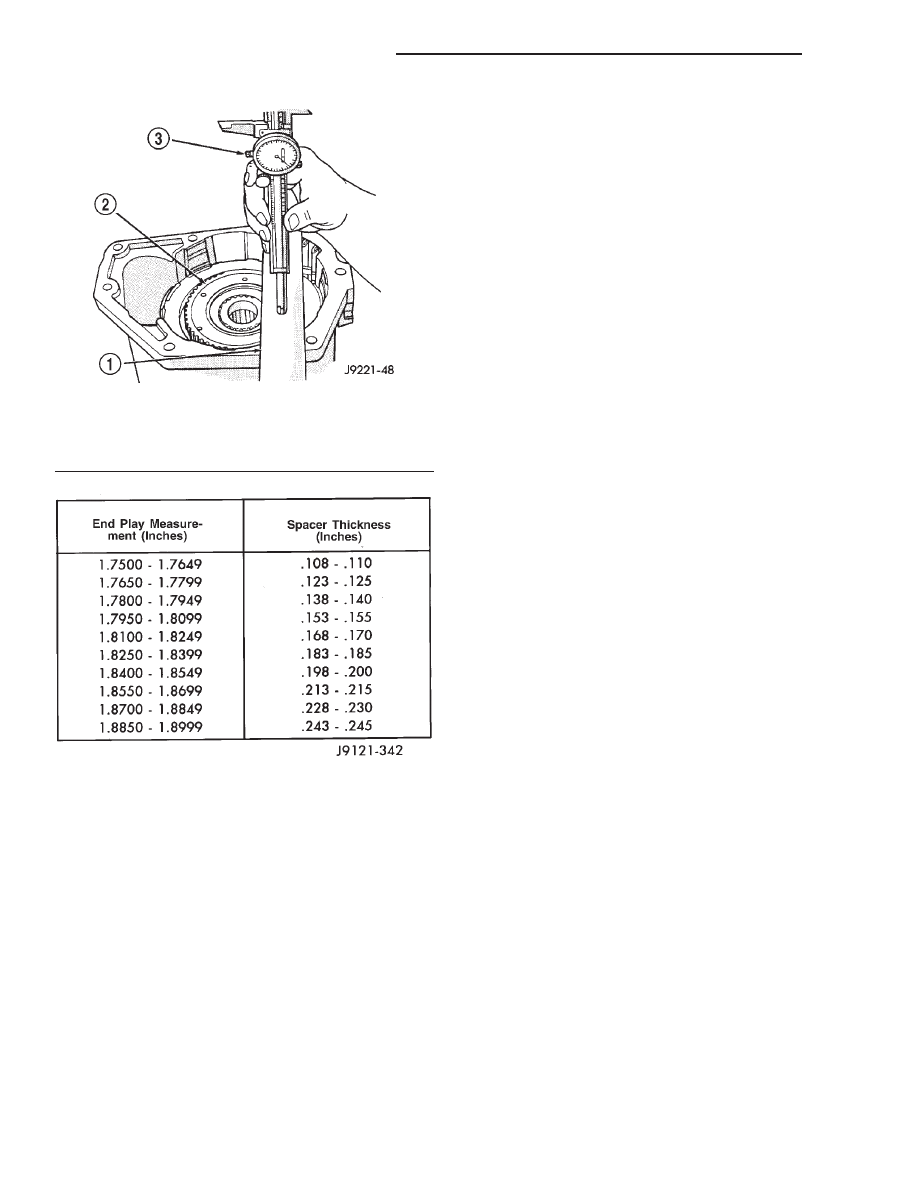
Fig. 305 Overdrive Piston Thrust Plate Measurement

1 – SPECIAL TOOL 6311
2 – DIRECT CLUTCH HUB THRUST BEARING SEAT
3 – SPECIAL TOOL C-4962

Fig. 306 Overdrive Piston Thrust Plate Selection

21 - 302

46RE AUTOMATIC TRANSMISSION

DN

DISASSEMBLY AND ASSEMBLY (Continued)

face. If distortion is severe or any surfaces are
heavily scored, the valve body will have to be
replaced.

CAUTION: Many of the valves and plugs, such as
the throttle valve, shuttle valve plug, 1-2 shift valve
and 1-2 governor plug, are made of coated alumi-
num. Aluminum components are identified by the
dark color of the special coating applied to the sur-
face (or by testing with a magnet). Do not sand alu-
minum valves or plugs under any circumstances.
This practice could damage the special coating
causing the valves/plugs to stick and bind.

Inspect the valves and plugs for scratches, burrs,

nicks, or scores. Minor surface scratches on steel
valves and plugs can be removed with crocus cloth
but do not round off the edges of the valve or
plug lands. 
Maintaining sharpness of these edges is
vitally important. The edges prevent foreign matter
from lodging between the valves and plugs and the
bore.

Inspect all the valve and plug bores in the valve

body. Use a penlight to view the bore interiors.
Replace the valve body if any bores are distorted or
scored. Inspect all of the valve body springs. The
springs must be free of distortion, warpage or broken
coils.

Check the two separator plates for distortion or

damage of any kind. Inspect the upper housing,
lower housing, 3-4 accumulator housing, and transfer
plate carefully. Be sure all fluid passages are clean
and clear. Check condition of the upper housing and

transfer plate check balls as well. The check balls
and ball seats must not be worn or damaged.

Trial fit each valve and plug in its bore to check

freedom of operation. When clean and dry, the valves
and plugs should drop freely into the bores.

Valve body bores do not change dimensionally with

use. If the valve body functioned correctly when new,
it will continue to operate properly after cleaning and
inspection. It should not be necessary to replace a
valve body assembly unless it is damaged in han-
dling.

The only serviceable valve body components are

listed below. The remaining valve body components
are serviced only as part of a complete valve body
assembly. Serviceable parts are:

• dual solenoid and harness assembly

• solenoid gasket

• solenoid case connector O-rings and shoulder

bolt

• switch valve and spring

• pressure adjusting screw and bracket assembly

• throttle lever

• manual lever and shaft seal

• throttle lever shaft seal, washer, and E-clip

• fluid filter and screws

• detent ball and spring

• valve body screws

• governor pressure solenoid

• governor pressure sensor and retaining clip

• park lock rod and E-clip

DN

46RE AUTOMATIC TRANSMISSION

21 - 303

CLEANING AND INSPECTION (Continued)

Fig.

307

Upper

Housing

V

alves,

Plug,

Springs

And

Brackets

21 - 304

46RE AUTOMATIC TRANSMISSION

DN

CLEANING AND INSPECTION (Continued)

TRANSMISSION

GENERAL INFORMATION

Inspect the transmission bushings during overhaul.

Bushing condition is important as worn, scored bush-
ings contribute to low pressures, clutch slip and
accelerated wear of other components. However, do
not replace bushings as a matter of course. Replace
bushings only when they are actually worn, or
scored.

Use recommended tools to replace bushings. The

tools are sized and designed to remove, install, and
seat bushings correctly. The bushing replacement
tools are included in Bushing Tool Set C-3887-B.

Pre-sized

service

bushings

are

available

for

replacement purposes. Only the sun gear bushings
are not serviced. Low cost of the sun gear assembly
makes it easier to simply replace the gear and bush-
ings as an assembly.

Heli-Coil inserts can be used to repair damaged,

stripped or worn threads in aluminum parts. These
inserts are available from most automotive parts
suppliers. Stainless steel inserts are recommended.

The use of crocus cloth is permissible where neces-

sary, providing it is used carefully. When used on
shafts, or valves, use extreme care to avoid rounding
off sharp edges. Sharp edges are vital as they pre-
vent foreign matter from getting between the valve
and valve bore.

Do not reuse oil seals, gaskets, seal rings, or

O-rings during overhaul. Replace these parts as a
matter of course. Also do not reuse snap rings or
E-clips that are bent or distorted. Replace these parts
as well.

Lubricate transmission parts with Mopar

t ATF

Plus 3, Type 7176, transmission fluid during over-
haul and assembly. Use petroleum jelly, Mopar

t Door

Ease, or Ru-Glyde to prelubricate seals, O-rings, and

thrust washers. Petroleum jelly can also be used to
hold parts in place during reassembly.

TRANSMISSION CASE CLEANING AND
INSPECTION

Clean the case in a solvent tank. Flush the case

bores and fluid passages thoroughly with solvent.
Dry the case and all fluid passages with compressed
air. Be sure all solvent is removed from the case and
that all fluid passages are clear.

NOTE: Do not use shop towels or rags to dry the
case (or any other transmission component) unless
they are made from lint-free materials. Lint will stick
to case surfaces and transmission components and
circulate throughout the transmission after assem-
bly. A sufficient quantity of lint can block fluid pas-
sages and interfere with valve body operation.

Inspect the case for cracks, porous spots, worn

bores, or damaged threads. Damaged threads can be
repaired with Helicoil thread inserts. However, the
case will have to be replaced if it exhibits any type of
damage or wear.

Lubricate the front band adjusting screw threads

with petroleum jelly and thread the screw part-way
into the case. Be sure the screw turns freely.

OVERRUNNING CLUTCH/LOW-REVERSE
DRUM/OVERDRIVE PISTON RETAINER

Clean the overrunning clutch assembly, clutch cam,

low-reverse drum, and overdrive piston retainer in
solvent. Dry them with compressed air after clean-
ing.

Inspect condition of each clutch part after cleaning.

Replace the overrunning clutch roller and spring
assembly if any rollers or springs are worn or dam-

1 – SHIFT VALVE COVER
2 – 1–2 SHIFT VALVE AND SPRING
3 – 2–3 SHIFT VALVE AND SPRING
4 – SHUTTLE VALVE SECONDARY SPRING, GUIDES, E-CLIP
5 – VALVE BODY
6 – SHUTTLE VALVE COVER
7 – SHUTTLE VALVE AND PRIMARY SPRING
8 – MANUAL VALVE
9 – 2–3 SHIFT VALVE GOVERNOR PLUG
10 – SHUTTLE VALVE PLUG
11 – 1–2 SHIFT VALVE GOVERNOR PLUG
12 – THROTTLE VALVE AND SPRING
13 – KICKDOWN VALVE AND DETENT
14 – VALVE AND PLUG COVER
15 – MANUAL LEVER DETENT BALL AND SPRING
16 – PRESSURE REGULATOR VALVE AND SPRING
17 – SWITCH VALVE AND SPRING

18 – THROTTLE PRESSURE ADJUSTING SCREW
19 – TRANSFER PLATE
20 – ADJUSTING SCREW BRACKET
21 – BOOST VALVE COVER
22 – LINE PRESSURE ADJUSTING SCREW
23 – BOOST VALVE AND PLUG
24 – BOOST VALVE SPRING
25 – VALVE AND SPRING RETAINER
26 – STIFFENER PLATE
27 – SEPARATOR PLATE
28 – SPRING
29 – REGULATOR VALVE THROTTLE PRESSURE PLUG
30 – SLEEVE
31 – REGULATOR VALVE PRESSURE PLUG
32 – 1–2 SHIFT CONTROL VALVE AND SPRING
33 – REGULATOR VALVE COVER

DN

46RE AUTOMATIC TRANSMISSION

21 - 305

CLEANING AND INSPECTION (Continued)


Content   ..  107  108  109  110   ..