Dodge Durango (DN). Manual - part 82
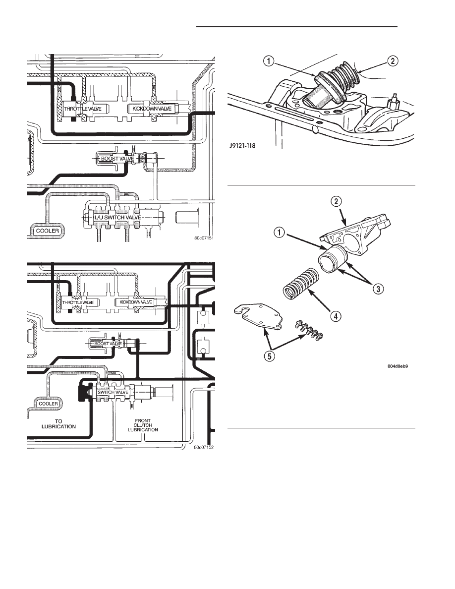
tion of a band or clutch. The accumulator consists of
a dual–land piston and a spring located in a bore in
the transmission case. The 3–4 accumulator is
located in a housing attached to the side of the valve
body (Fig. 47).
OPERATION
Both the accumulator and the 3–4 accumulator
function the same. Line pressure is directed between
the lands of the piston (Fig. 48), bottoming it against
the accumulator plate. The accumulator stays in this
position after the transmission is placed into a Drive
position. When the 1–2 upshift occurs (Fig. 49), line
pressure is directed to the large end of the piston and
then to the kickdown servo. As the line pressure
reaches the accumulator, the combination of spring
pressure and line pressure forces the piston away
from the accumulator plate. This causes a balanced
pressure situation, which results in a cushioned band
application. After the kickdown servo has become
immovable, line pressure will finish pushing the
accumulator up into its bore. When the large end of
Fig. 44 Boost Valve Before Lock-up
Fig. 45 Boost Valve After Lock-up
Fig. 46 Accumulator
1 – ACCUMULATOR PISTON
2 – PISTON SPRING
Fig. 47 3–4 Accumulator and Housing
1 – ACCUMULATOR PISTON
2 – 3–4 ACCUMULATOR HOUSING
3 – TEFLON SEALS
4 – PISTON SPRING
5 – COVER PLATE AND SCREWS
21 - 194
46RE AUTOMATIC TRANSMISSION
DN
DESCRIPTION AND OPERATION (Continued)