Dodge Durango (DN). Manual - part 76


  Index      Dodge     Dodge Durango (DN) - service repair manual 2000 year


Search            


Content   ..  74  75  76  77   ..


Dodge Durango (DN). Manual - part 76


Exceptions to this policy are the use of special dyes
to aid in detecting fluid leaks.

Various “special” additives and supplements exist

that claim to improve shift feel and/or quality. These
additives and others also claim to improve converter
clutch operation and inhibit overheating, oxidation,
varnish, and sludge. These claims have not been sup-
ported to the satisfaction of DaimlerChrysler and
these additives must not be used. The use of trans-
mission “sealers” should also be avoided, since they
may adversely affect the integrity of transmission
seals.

OPERATION

The automatic transmission fluid is selected based

upon several qualities. The fluid must provide a high
level of protection for the internal components by
providing a lubricating film between adjacent metal
components. The fluid must also be thermally stable
so that it can maintain a consistent viscosity through
a large temperature range. If the viscosity stays con-
stant through the temperature range of operation,
transmission operation and shift feel will remain con-
sistent. Transmission fluid must also be a good con-
ductor of heat. The fluid must absorb heat from the
internal transmission components and transfer that
heat to the transmission case.

TORQUE CONVERTER

DESCRIPTION

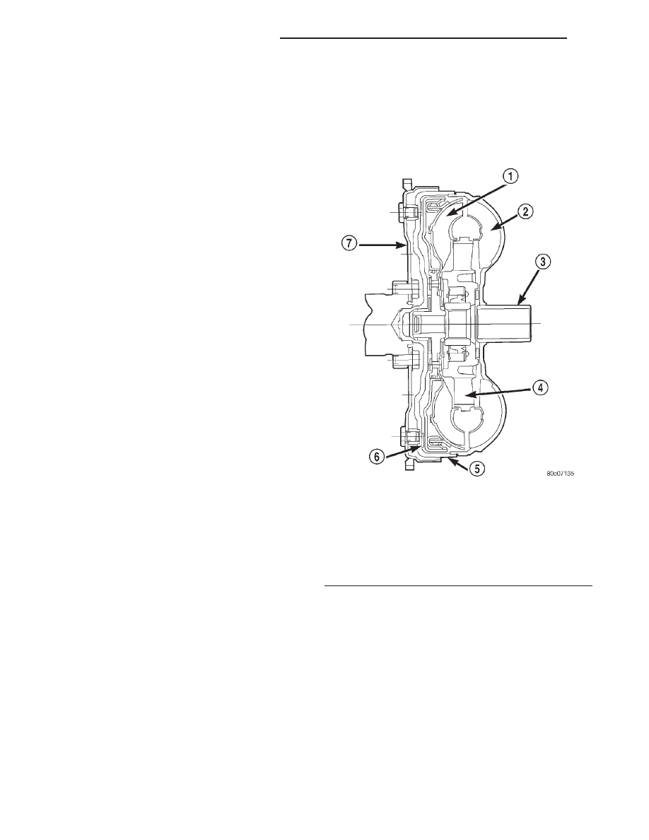
The torque converter (Fig. 9) is a hydraulic device

that couples the engine crankshaft to the transmis-
sion. The torque converter consists of an outer shell
with an internal turbine, a stator, an overrunning
clutch, an impeller and an electronically applied con-
verter clutch. The converter clutch provides reduced
engine

speed

and

greater

fuel

economy

when

engaged. Clutch engagement also provides reduced
transmission

fluid

temperatures.

The

converter

clutch engages in third gear. The torque converter
hub drives the transmission oil (fluid) pump.

The torque converter is a sealed, welded unit that

is not repairable and is serviced as an assembly.

CAUTION: The torque converter must be replaced if
a transmission failure resulted in large amounts of
metal or fiber contamination in the fluid. If the fluid
is contaminated, flush the fluid cooler and lines.

Fig. 9 Torque Converter Assembly

1 – TURBINE
2 – IMPELLER
3 – HUB
4 – STATOR
5 – FRONT COVER
6 – CONVERTER CLUTCH DISC
7 – DRIVE PLATE

21 - 170

46RE AUTOMATIC TRANSMISSION

DN

DESCRIPTION AND OPERATION (Continued)

IMPELLER

The impeller (Fig. 10) is an integral part of the

converter housing. The impeller consists of curved
blades placed radially along the inside of the housing
on the transmission side of the converter. As the con-
verter housing is rotated by the engine, so is the
impeller, because they are one and the same and are
the driving member of the system.

Fig. 10 Impeller

1 – ENGINE FLEXPLATE
2 – OIL FLOW FROM IMPELLER SECTION INTO TURBINE

SECTION

3 – IMPELLER VANES AND COVER ARE INTEGRAL

4 – ENGINE ROTATION
5 – ENGINE ROTATION

DN

46RE AUTOMATIC TRANSMISSION

21 - 171

DESCRIPTION AND OPERATION (Continued)

TURBINE

The turbine (Fig. 11) is the output, or driven, mem-

ber of the converter. The turbine is mounted within
the housing opposite the impeller, but is not attached
to the housing. The input shaft is inserted through
the center of the impeller and splined into the tur-
bine. The design of the turbine is similar to the
impeller, except the blades of the turbine are curved
in the opposite direction.

Fig. 11 Turbine

1 – TURBINE VANE
2 – ENGINE ROTATION
3 – INPUT SHAFT

4 – PORTION OF TORQUE CONVERTER COVER
5 – ENGINE ROTATION
6 – OIL FLOW WITHIN TURBINE SECTION

21 - 172

46RE AUTOMATIC TRANSMISSION

DN

DESCRIPTION AND OPERATION (Continued)

STATOR

The stator assembly (Fig. 12) is mounted on a sta-

tionary shaft which is an integral part of the oil
pump. The stator is located between the impeller and
turbine within the torque converter case (Fig. 13).
The stator contains an over-running clutch, which
allows the stator to rotate only in a clockwise direc-
tion. When the stator is locked against the over-run-
ning clutch, the torque multiplication feature of the
torque converter is operational.

TORQUE CONVERTER CLUTCH (TCC)

The TCC (Fig. 14) was installed to improve the

efficiency of the torque converter that is lost to the
slippage of the fluid coupling. Although the fluid cou-
pling provides smooth, shock–free power transfer, it
is natural for all fluid couplings to slip. If the impel-
ler and turbine were mechanically locked together, a
zero slippage condition could be obtained. A hydraulic
piston was added to the turbine, and a friction mate-
rial was added to the inside of the front cover to pro-
vide this mechanical lock-up.

OPERATION

The converter impeller (Fig. 15) (driving member),

which is integral to the converter housing and bolted
to the engine drive plate, rotates at engine speed.
The converter turbine (driven member), which reacts
from fluid pressure generated by the impeller, rotates
and turns the transmission input shaft.

TURBINE

As the fluid that was put into motion by the impel-

ler blades strikes the blades of the turbine, some of

Fig. 12 Stator Components

1 – CAM (OUTER RACE)
2 – ROLLER
3 – SPRING
4 – INNER RACE

Fig. 13 Stator Location

1 – STATOR
2 – IMPELLER
3 – FLUID FLOW
4 – TURBINE

Fig. 14 Torque Converter Clutch (TCC)

1 – IMPELLER FRONT COVER
2 – THRUST WASHER ASSEMBLY
3 – IMPELLER
4 – STATOR
5 – TURBINE
6 – FRICTION DISC

DN

46RE AUTOMATIC TRANSMISSION

21 - 173

DESCRIPTION AND OPERATION (Continued)


Content   ..  74  75  76  77   ..