Dodge Durango (DN). Manual - part 46


  Index      Dodge     Dodge Durango (DN) - service repair manual 2000 year


Search            


Content   ..  44  45  46  47   ..


Dodge Durango (DN). Manual - part 46


Front Servo Apply Air Test

Apply air pressure to the front servo apply pas-

sage. The servo rod should extend and cause the
band to tighten around the drum. Spring pressure
should release the servo when air pressure is
removed.

Rear Servo Air Test

Apply air pressure to the rear servo apply passage.

The servo rod should extend and cause the band to
tighten around the drum. Spring pressure should
release the servo when air pressure is removed.

CONVERTER HOUSING FLUID LEAK
DIAGNOSIS

When diagnosing converter housing fluid leaks,

two items must be established before repair.

(1) Verify that a leak condition actually exists.
(2) Determined the true source of the leak.
Some suspected converter housing fluid leaks may

not be leaks at all. They may only be the result of
residual fluid in the converter housing, or excess
fluid spilled during factory fill or fill after repair.
Converter

housing

leaks

have

several

potential

sources. Through careful observation, a leak source
can be identified before removing the transmission
for repair. Pump seal leaks tend to move along the
drive hub and onto the rear of the converter. Pump
O-ring or pump body leaks follow the same path as a
seal leak (Fig. 68). Pump vent or pump attaching bolt
leaks are generally deposited on the inside of the
converter housing and not on the converter itself
(Fig. 68). Pump seal or gasket leaks usually travel
down the inside of the converter housing. Front band
lever pin plug leaks are generally deposited on the
housing and not on the converter.

TORQUE CONVERTER LEAK POINTS

Possible sources of converter leaks are:
(1) Leaks at the weld joint around the outside

diameter weld (Fig. 69).

(2) Leaks at the converter hub weld (Fig. 69).

CONVERTER HOUSING AREA LEAK CORRECTION

(1) Remove converter.
(2) Tighten front band adjusting screw until band

is tight around front clutch retainer. This prevents
front/rear clutches from coming out when oil pump is
removed.

(3) Remove oil pump and remove pump seal.

Inspect pump housing drainback and vent holes for
obstructions. Clear holes with solvent and wire.

(4) Inspect pump bushing and converter hub. If

bushing is scored, replace it. If converter hub is
scored, either polish it with crocus cloth or replace
converter.

(5) Install new pump seal, O-ring, and gasket.

Replace oil pump if cracked, porous or damaged in
any way. Be sure to loosen the front band before
installing the oil pump, damage to the oil pump seal
may occur if the band is still tightened to the front
clutch retainer.

(6) Loosen kickdown lever pin access plug three

turns. Apply Loctite 592, or Permatex No. 2 to plug
threads and tighten plug to 17 N·m (150 in. lbs.)
torque.

(7) Adjust front band.

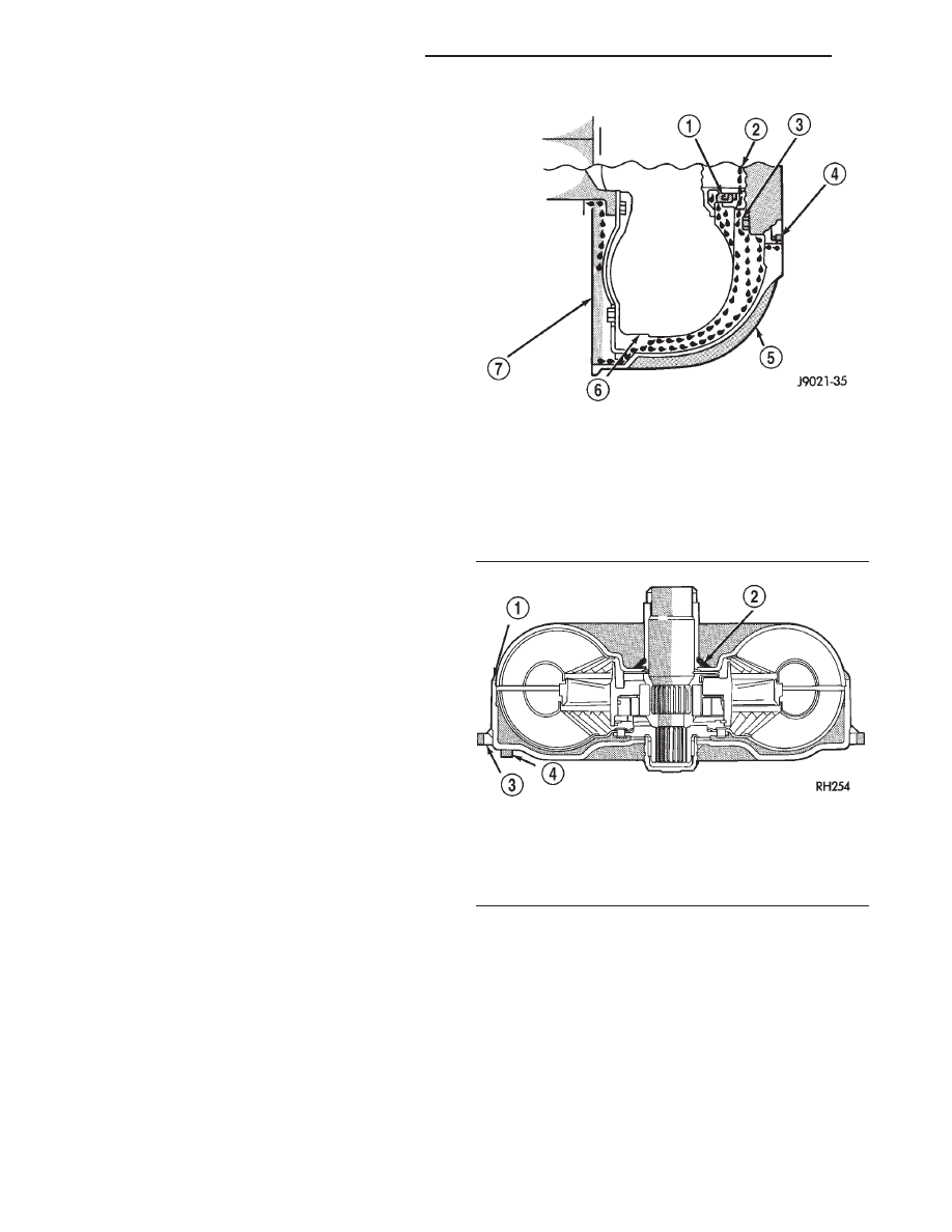
Fig. 68 Converter Housing Leak Paths

1 – PUMP SEAL
2 – PUMP VENT
3 – PUMP BOLT
4 – PUMP GASKET
5 – CONVERTER HOUSING
6 – CONVERTER
7 – REAR MAIN SEAL LEAK

Fig. 69 Converter Leak Points—Typical

1 – OUTSIDE DIAMETER WELD
2 – TORQUE CONVERTER HUB WELD
3 – STARTER RING GEAR
4 – LUG

21 - 50

42/44RE AUTOMATIC TRANSMISSION

DN

DIAGNOSIS AND TESTING (Continued)

(8) Lubricate pump seal and converter hub with

transmission fluid or petroleum jelly and install con-
verter.

(9) Install transmission and converter housing

dust shield.

(10) Lower vehicle.

DIAGNOSIS TABLES AND CHARTS—RE
TRANSMISSION

The diagnosis charts provide additional reference

when diagnosing a transmission fault. The charts

provide general information on a variety of transmis-
sion, overdrive unit and converter clutch fault condi-
tions.

The hydraulic flow charts in the Schematics and

Diagrams section of this group, outline fluid flow and
hydraulic circuitry. Circuit operation is provided for
neutral, third, fourth and reverse gear ranges. Nor-
mal working pressures are also supplied for each of
the gear ranges.

DIAGNOSIS CHARTS

CONDITION

POSSIBLE CAUSES

CORRECTION

HARSH ENGAGEMENT
(FROM NEUTRAL TO
DRIVE OR REVERSE)

1. Fluid Level Low

1. Add Fluid

2. Throttle Linkage Misadjusted

2. Adjust linkage - setting may be too long.

3. Mount and Driveline Bolts Loose

3. Check engine mount, transmission mount,
propeller shaft, rear spring to body bolts, rear
control arms, crossmember and axle bolt
torque. Tighten loose bolts and replace
missing bolts.

4. U-Joint Worn/Broken

4. Remove propeller shaft and replace
U-Joint.

5. Axle Backlash Incorrect

5. Check per Service Manual. Correct as
needed.

6. Hydraulic Pressure Incorrect

6. Check pressure. Remove, overhaul or
adjust valve body as needed.

7. Band Misadjusted.

7. Adjust rear band.

8. Valve Body Check Balls Missing.

8. Inspect valve body for proper check ball
installation.

9. Axle Pinion Flange Loose.

9. Replace nut and check pinion threads
before installing new nut. Replace pinion gear
if threads are damaged.

10. Clutch, band or planetary
component damaged.

10. Remove, disassemble and repair
transmission as necessary.

11. Converter Clutch Faulty.

11. Replace converter and flush cooler and
line before installing new converter.

DELAYED ENGAGEMENT
(FROM NEUTRAL TO
DRIVE OR REVERSE)

1. Fluid Level Low.

1. Correct level and check for leaks.

2. Filter Clogged.

2. Change filter.

3. Gearshift Linkage Misadjusted.

3. Adjust linkage and repair linkage if worn or
damaged.

4. Torque Converter Drain Back (Oil
drains from torque converter into
transmission sump)

4. If vehicle moves normally after 5 seconds
after shifting into gear, no repair is necessary.
If longer, inspect pump bushing for wear.
Replace pump house.

5. Rear Band Misadjusted.

5. Adjust band.

DN

42/44RE AUTOMATIC TRANSMISSION

21 - 51

DIAGNOSIS AND TESTING (Continued)

CONDITION

POSSIBLE CAUSES

CORRECTION

6. Valve Body Filter Plugged.

6. Replace fluid and filter. If oil pan and old
fluid were full of clutch disc material and/or
metal particles, overhaul will be necessary.

7. Oil Pump Gears Worn/Damaged.

7. Remove transmission and replace oil
pump.

8. Governor Circuit and Solenoid Valve
Electrical Fault.

8. Test with DRB scan tool and repair as
required.

9. Hydraulic Pressure Incorrect.

9. Perform pressure test, remove transmission
and repair as needed.

10. Reaction Shaft Seal Rings
Worn/Broken.

10. Remove transmission, remove oil pump
and replace seal rings.

11. Rear Clutch/Input Shaft, Rear
Clutch Seal Rings Damaged.

11. Remove and disassemble transmission
and repair as necessary.

12. Regulator Valve Stuck.

12. Clean.

13. Cooler Plugged.

13. Transfer case failure can plug cooler.

NO DRIVE RANGE
(REVERSE OK)

1. Fluid Level Low.

1. Add fluid and check for leaks if drive is
restored.

2. Gearshift Linkage/Cable Loose/
Misadjusted.

2. Repair or replace linkage components.

3. Rear Clutch Burnt.

3. Remove and disassemble transmission and
rear clutch and seals. Repair/replace worn or
damaged parts as needed.

4. Valve Body Malfunction.

4. Remove and disassemble valve body.
Replace assembly if any valves or bores are
damaged.

5. Transmission Overrunning Clutch
Broken.

5. Remove and disassemble transmission.
Replace overrunning clutch.

6. Input Shaft Seal Rings Worn/
Damaged.

6. Remove and disassemble transmission.
Replace seal rings and any other worn or
damaged parts.

7. Front Planetary Failed Broken.

7. Remove and repair.

NO DRIVE OR REVERSE
(VEHICLE WILL NOT
MOVE)

1. Fluid Level Low.

1. Add fluid and check for leaks if drive is
restored.

2. Gearshift Linkage/Cable Loose/
Misadjusted.

2. Inspect, adjust and reassemble linkage as
needed. Replace worn/damaged parts.

3. U-Joint/Axle/Transfer Case Broken.

3. Perform preliminary inspection procedure
for vehicle that will not move. Refer to
procedure in diagnosis section.

4. Filter Plugged.

4. Remove and disassemble transmission.
Repair or replace failed components as
needed. Replace filter. If filter and fluid
contained clutch material or metal particles,
an overhaul may be necessary. Perform lube
flow test. Flush oil. Replace cooler as
necessary.

5. Oil Pump Damaged.

5. Perform pressure test to confirm low
pressure. Replace pump body assembly if
necessary.

21 - 52

42/44RE AUTOMATIC TRANSMISSION

DN

DIAGNOSIS AND TESTING (Continued)

CONDITION

POSSIBLE CAUSES

CORRECTION

6. Valve Body Malfunctioned.

6. Check and inspect valve body. Replace
valve body (as assembly) if any valve or bore
is damaged. Clean and reassemble correctly
if all parts are in good condition.

7. Transmission Internal Component
Damaged.

7. Remove and disassemble transmission.
Repair or replace failed components as
needed.

8. Park Sprag not Releasing - Check
Stall Speed, Worn/Damaged/Stuck.

8. Remove, disassemble, repair.

9. Torque Converter Damage.

9. Inspect and replace as required.

SHIFTS DELAYED OR
ERRATIC (SHIFTS ALSO
HARSH AT TIMES)

1. Fluid Level Low/High.

1. Correct fluid level and check for leaks if
low.

2. Fluid Filter Clogged.

2. Replace filter. If filter and fluid contained
clutch material or metal particles, an overhaul
may be necessary. Perform lube flow test.

3. Throttle Linkage Misadjusted.

3. Adjust linkage as described in service
section.

4. Throttle Linkage Binding.

4. Check cable for binding. Check for return
to closed throttle at transmission.

5. Gearshift Linkage/Cable
Misadjusted.

5. Adjust linkage/cable as described in service
section.

6. Clutch or Servo Failure.

6. Remove valve body and air test clutch, and
band servo operation. Disassemble and repair
transmission as needed.

7. Governor Circuit Electrical Fault.

7. Test using DRB scan tool and repair as
required.

8. Front Band Misadjusted.

8. Adjust band.

9. Pump Suction Passage Leak.

9. Check for excessive foam on dipstick after
normal driving. Check for loose pump bolts,
defective gasket. Replace pump assembly if
needed.

NO REVERSE (D RANGES
OK)

1. Gearshift Linkage/Cable
Misadjusted/Damaged.

1. Repair or replace linkage parts as needed.

2. Park Sprag Sticking.

2. Replace overdrive annulus gear.

3. Rear Band Misadjusted/Worn.

3. Adjust band; replace.

4. Valve Body Malfunction.

4. Remove and service valve body. Replace
valve body if any valves or valve bores are
worn or damaged.

5. Rear Servo Malfunction.

5. Remove and disassemble transmission.
Replace worn/damaged servo parts as
necessary.

6. Direct Clutch in Overdrive Worn

6. Disassemble overdrive. Replace worn or
damaged parts.

7. Front Clutch Burnt.

7. Remove and disassemble transmission.
Replace worn, damaged clutch parts as
required.

DN

42/44RE AUTOMATIC TRANSMISSION

21 - 53

DIAGNOSIS AND TESTING (Continued)


Content   ..  44  45  46  47   ..